A voltage regulator is used to regulate or stabilize the voltage level for specific purpose. Voltage fluctuations are never acceptable for any appliance or equipment, because it may damage the electrical appliances etc. When a steady, reliable voltage is needed, then voltage regulator is the preferred device. Despite varying inputs or load conditions a stabilizer generates a fixed output voltage that remains constant. so we can say that voltage regulator acts as a buffer for protecting components from damages. A voltage regulator is a device with a simple feed- forward design and it uses negative feedback control loops.
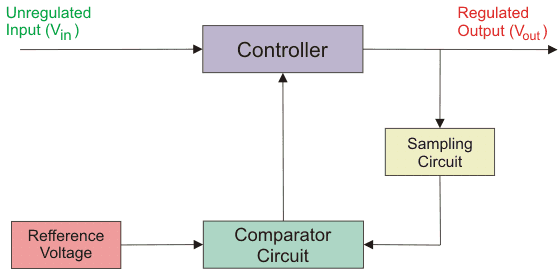
From above diagram you can see that unregulated voltage enters the controller. A part of the output is fed to the sampling circuit, which in turn feeds it back to the comparator circuit. The voltage level is compared with the reference voltage. Appropriate corrections are made and send back to the controller. In this manner, the voltage is regulated.
Types of Voltage Regulator
There are mainly two basic categories of voltage regulator i.e. line regulation and load regulation. The purpose of line regulation is to maintain a nearly constant output voltage when the input voltage varies. The purpose of load regulation is to maintain a nearly constant output voltage when the load varies.
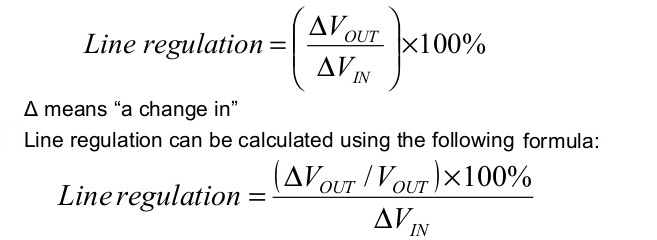
In the case of line regulation any change in input (line) voltage does not significantly affect the output voltage of a regulator (within certain limits). Therefore we can define line regulation as the percentage change in the output voltage for a given change in the input voltage.
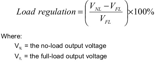
Load regulation can be defined as the percentage change in the output voltage from no-load (NL) to full-load (FL).
There are mainly two types of voltage regulators i.e. linear voltage regulator and switching voltage regulators.
Linear Voltage Regulator
The operation of linear voltage regulator is similar to a voltage divider. This regulator uses the FET in the ohmic region. The resistance of the linear voltage regulator changes with the load and gives a constant voltage output hence behaving like a stabilizer.
Below is a picture of LM7805, one of the popular linear voltage regulator. This is useful for low cost low power applications. There are further two types of linear voltage regulators i.e. series voltage regulator and shunt voltage regulator.
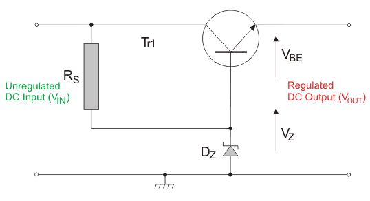
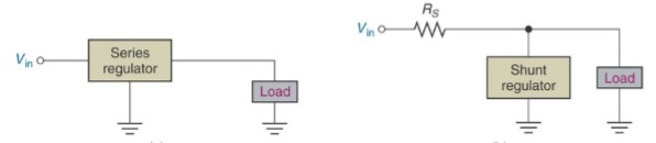
Series Voltage Regulator: A simple series voltage regulator has a variable element like a transistor whose resistance varies on a variable input voltage, this helps to keep the output voltage constant and steady. A series voltage regulator uses a variable element placed in series with the load. By changing the resistance of that series element, the voltage dropped across it can be changed. The voltage across the load remains constant. The amount of current drawn is effectively used by the load. This is the main advantage of the series voltage regulator.
Shunt Voltage Regulator: This works similar to the series voltage regulator but is connected in the circuit in parallel or in shunt connection. All the excess voltage is sent to the ground. Shunt voltage regulator is mainly useful for precision current limiters, voltage monitoring, error amplifiers etc.
Shunt regulators are used in low output voltage switching power supplies, current source and sink circuits, error amplifiers, adjustable voltage or current linear and switching power supplies, voltage monitoring, analog and digital circuits that require precision references and precision current limiters etc.
Advantages and disadvantages of linear voltage regulator
Advantages of Linear Voltage Regulators: Cheaper as compared to other type, fast response time, having lower electromagnetic interference and noise as compared to switching voltage regulators and work as stabilizer and provides constant output voltage for low power applications.
Disadvantages of Linear Voltage Regulators: Efficiency is less, high heat generating therefore need additional heat sink and space and output can not increase higher than the input.
Switching Voltage Regulators
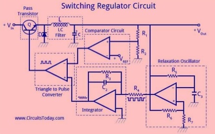
The switching regulator is a type of regulator circuit in which its efficient transfer of power to the load is greater than series and shunt regulators because the transistor is not always conducting. The switching regulator passes voltage to the load in pulses, which then filtered to provide a smooth dc voltage. The switching type voltage regulator is more efficient than the linear series or shunt type.
This type regulator or stabilizer is ideal for high current applications since less power is dissipated. Voltage regulation in a switching regulator is achieved by the on and off action limiting the amount of current flow based on the varying line and load conditions. With switching regulators 90% efficiencies can be achieved.
Advantages of Switching Voltage Regulators
- power conversion efficiency than linear voltage regulators is high
- heat sinks is not necessary
- useful if input and output voltages are having much difference
Diadvantages of Switching Voltage Regulators
- Expansive
- electromagnetic interference and noise is high
- Is more complex
Configurations of Switching Voltage Regulators
Switching regulators come in different configurations as mentioned below:
Switching Regulator Step-Down Configuration
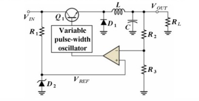
With the step-down (output is less than the input) configuration the control element Q1 is pulsed on and off at variable rate based on the load current. The pulsations are filtered out by the LC filter.
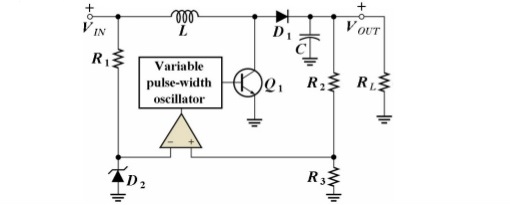
Switching Regulator Step-up configuration
The difference is in the placement of the inductor and the fact that Q1 is shunt configured. During the time when Q1 is off the VL adds to VC stepping the voltage up by some amount.
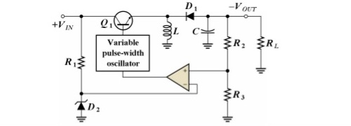
Switching Regulator Voltage-inverter configuration
Output voltage is of opposite polarity of the input. This is achieved by VL forward-biasing reverse-biased diode during the off times producing current and charging the capacitor for voltage production during the off times. With switching regulators 90% efficiency is achievable.