Power transformer is most costly and essential equipment of an electrical system. It is well known fact that power transformers are the heart of the power systems which enables to establish very large power systems networks. Failure of any transformer will create critical situation in power distribution network hence extra attention is required in commissioning, maintenance & protection of the power transformers. The periodical preventive maintenance is mandatory and will improve the life period of power transformer. For getting high performance and long functional life of the transformer, it is desired to perform various maintenance activities. Not only that, a power transformer also requires various maintenance actions including measurement and testing of different parameters of the transformer.
EMF Equation of a Transformer
As soon as the sinusoidal voltage is applied to the primary winding of a transformer, alternating flux ϕm sets up in the iron core of the transformer. This sinusoidal flux links with both primary and secondary winding. The function of flux is a sine function. The rate of change of flux with respect to time is derived mathematically.
Let
- ϕm be the maximum value of flux in Weber
- f be the supply frequency in Hz
- N1 is the number of turns in the primary winding
- N2 is the number of turns in the secondary winding
- Φ is the flux per turn in Weber
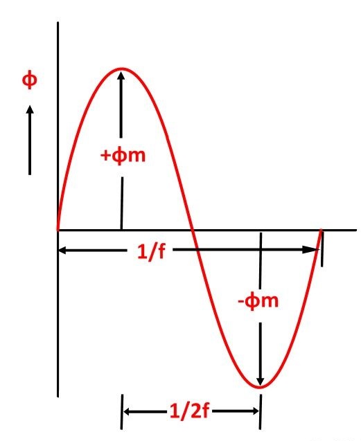
As shown in the above figure that the flux changes from + ϕm to – ϕm in half a cycle of 1/2f seconds.
By Faraday’s Law
Let E1 is the emf induced in the primary winding
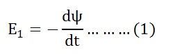
Where Ψ = N1ϕ
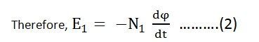
Since ϕ is due to AC supply ϕ = ϕm Sinwt
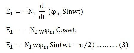
So the induced emf lags flux by 90 degrees.
Maximum valve of emf
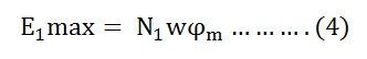
But w = 2πf
![]()
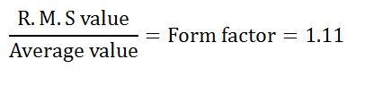
Root mean square RMS value is
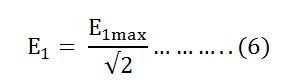
Putting the value of E1max in equation (6) we get
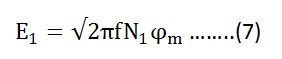
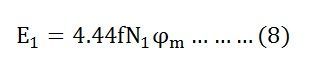
Putting the value of π = 3.14 in the equation (7) we will get the value of E1 as
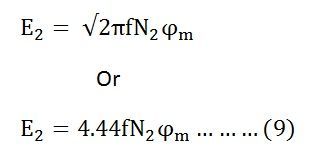
Similarly
Now, equating the equation (8) and (9) we get
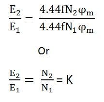
The above equation is called the turn ratio where K is known as transformation ratio.
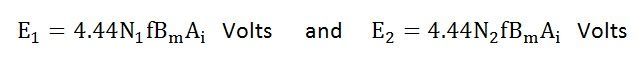
The equation (8) and (9) can also be written as shown below using the relation
(ϕm = Bm x Ai) where Ai is the iron area and Bm is the maximum value of flux density.
For a sinusoidal wave