
Before starting the switchgear testing an approved testing & commissioning engineer should be appointed in order to thoroughly review all the applicable drawings and specification, and to become totally familiar with all systems and the design intent. Experience certificate of T&C engineer to be submitted for client approval and test and commissioning should be done under the manufacturer supervision.
The commissioning engineer shall attend site during the final stage of construction works to supervise the installation and to ensure that all commissioning devices and other facilities required for the system commissioning are correctly installed.
Switchgear system to be factory tested for all the accessories like circuit breaker, current transformer, voltage transformer, ammeter, volt meter etc. It include the testing of the contact resistance of circuit breaker, winding resistance of the CT & VT, Polarity test & insulation resistance of the CT & VT, primary injection test for CT, High voltage test etc.
A survey of access requirements will be undertaken to ensure access to all items of the substation for commissioning purposes.
Tools & Equipment’s
Following tools, instruments and equipment shall be arranged:
- Electrician hand tools
- Helpers tool box
- Electric drill, cutter
- Hydraulic pulley
- Step ladders
- Torque wench
- Power Supply: Single-phase & 3-phase power where it is needed.
- Ohm meter, clamp meter, insulation tester. Earth tester, continuity tester etc–
- Spirit Level
- Calibrated megger & multimetre
- Calibrated CT Testing kit
- Calibrated Winding resistance Testing kit
- Calibrated HV kit
- Calibrated Relay Testing kit
Bus bar Torque Test: After installation of the switchboards, all the bus bar bolts are torque tested as per manufacturer’s recommendations with a torque wrench.
Breaker-to-Breaker Resistance Measurement: Breaker-to-Breaker resistance is measured by connecting a micro-ohm meter between adjacent panels by applying 100A DC for 10 seconds for each phase. The above said is repeated for other phases and other breakers also.
CT Testing
Insulation and causes of insulation failure
Because measuring insulation with a ohmmeter is part of a wider preventive maintenance policy, it is important to understand the different possible causes of insulation performance deterioration so that you can take steps to correct it. It is possible to divide these causes of insulation failure into five groups, while keeping in mind, if no corrective
measures are implemented, these different causes are superimposed, leading to insulation breakdown and
equipment failure.
Electrical stresses: Mainly linked to over voltages and under voltages.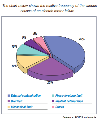
Mechanical stresses: Frequent start-up and shutdown sequences can cause mechanical stresses. Also, balancing problems on rotating machinery and any direct stress to the cables and the installations in general.
Chemical stresses: The proximity of chemicals, oils, corrosive vapors and dust, in general, affects the insulation performance of the materials.
Stresses linked to temperature variations: When combined with the mechanical stresses caused by the start-up and shutdown sequences, expansion and contraction stresses affect the properties of the insulating materials. Operation at extreme temperatures also leads to aging of the materials.
Environmental contamination: The build-up of mold and particulate deposits in warm, moist environments also contributes to the deterioration of installations’ insulation properties.
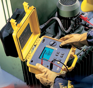
Insulation Resistance Measurement in Switchgear
Insulation resistance measurement is based on Ohm’s Law. By injecting a known DC voltage lower than the voltage for dielectric testing and then measuring the current flowing, it is very simple to determine the value of the resistance. In principle, the value of the insulation resistance is very high but not infinite, so by measuring the low current flowing, the ohmmeter indicates the insulation resistance value, providing a result in kW, MW, GW and also TW (on some models). This resistance characterizes the quality of the insulation between two conductors and gives
a good indication of the risks of leakage currents flowing.
A number of factors affect the value of the insulation resistance and therefore the value of the current flowing when a constant voltage is applied to the circuit being tested.
Measuring insulation resistance of C.T Primary secondary windings using 5kV Megger in a Switchgear.
Voltage to be applied
- Primary to Earth – 5kV for 1 minute.
- Secondary to Earth – 500V for 1 minute.
- Secondary to Primary – 500V for 1 minute.
Polarity check:
The DC voltage test momentarily imposes a small DC voltage on one side of a CT (Primary) and the direction of the momentary deflection of a meter on the opposite side (Secondary) of the CT is noted and compared with polarity marks.
Winding resistance Test: The secondary winding resistance of the CT is measured for each phase.
Ratio Test: Applying the current in the primary and by measuring the secondary current do the ratio test. Then dividing the value of the primary current by the secondary current checks the ratio of the CT. (This is to be done for all phases).
Magnetizing Curve: Knee point voltage and Magnetization curve have to be tested by using Current transformer test kit (MCT).
VT Testing
Insulation Resistance Measurement: Measuring insulation resistance of V.T Primary &secondary windings using 5kV Megger.
Voltage to be applied
- Primary to Earth – 5kV for 1 minute.
- Secondary to Earth – 500V for 1 minute.
- Secondary to Primary – 500V for 1 minute.
Polarity check: The check is made by imposing a small DC voltage on VT (Primary) to the earth and the direction of the momentary deflection of a sensitive voltmeter on the opposite side (Secondary) to the earth of the VT is noted.
Winding resistance Test: The primary and secondary winding resistance of the VT with respect to their neutrals is measured.
Ratio Test: Applying the three-phase voltage on the primary side and by measuring the secondary voltage for each phase does the ratio test. Then dividing the value of the primary voltage by the secondary voltage checks the ratio of the YT.
Relay Testing of Switchgear
All the relays are to be tested by secondary injection through CT and YT terminals using the secondary injection kit according to the manuals & test formats given.
Ammeter & Volt Meter Functional Test
All the Ammeter’s & volt meter’s are to be tested by secondary injection through CT and VT terminals using the secondary injection kit according to the manuals & test formats given.
Functional Checks
Functional test is to be done according to the drawings given. This test is proving interlocks; operations, tripping & alarms are as per the design.
High Voltage Test for Switchgear
High voltage test is done by applying 80% of factory-tested voltage. While doing the HV test the steps to be followed are:
- All CTs circuits are shorted.
- All VTs must be isolated.
- All the CBs are made into service.
- For doing ‘R’ phase the other phases are shorted and earthed.
- Before HV test 5kVmegger is to be done.
- HV test as said above is done for l minute and the leakage current is recorded from the kit.
- After HV test 5kV megger is to be done.
The above said is also repeated for other phases.
Primary Injection Test
Primary injection is done by applying current in primary of the CT and measuring the current up to the last point of the secondary circuit by making all the CT circuits through. This test is proving the secondary circuit of CT’s is proper.

Switch gear is also a important electric tools. It is safe and easy to working. You can easily check your electricity line. I always doing working by this power tools.
Few corrections are needed.IR values in K Ohms, MOhms,GOhms,and TOhms, not KW …..
Few laces VTs are mentioned YT