
As a standard practice installer or contractor shall arrange for the witnessing of the following tests on the fully equipped switchboards (main, submain distribution boards and Motor Control Centers MCC) including primary bus bars and connections at the factory, in accordance with IEC 439-1:
- High voltage power frequency tests on main and auxiliary circuits
- Dielectric/insulation resistance tests
- Ground fault tests
- Electrical operation of circuit breakers control circuits at the appropriate voltage limits
- Mechanical operations tests and tests to certify correct functioning of interlocks.
- Primary injection tests
- Secondary injection tests
- Milli volt drop tests
Following tests shall be carried out after the equipment has been completely erected and connected up
on site:
Power frequency voltage tests on the completed switchgear
Insulation resistance tests on all main and secondary circuits
Secondary injection tests
Calibration checks on ammeters, voltmeters and any other instruments
Testing at normal voltage to prove that closing and tripping from local and remote control points, tripping from relays and protective gear, interlocks, alarm and indications, etc are satisfactory. At the end of tests, the protective relays and breaker tripping times shall be set in accordance with
the approved discrimination coordination.
Detailed Check List for Panels T&C
a) Effectiveness of mechanical actuating elements
b) Door interlocks
c) Interconnection conductor sizes, laying and clamping/screwing
d) Visual inspection of degree of protection, creepage and clearance distances
e) Labels for feeders and circuit indications
f) Supply of operational instructions, wiring diagrams, technical data of equipment used
g) Inspection and operational testing of the factory built assembly
h) Electrical controls and sequence of operation
i) Physical verification of drawings, including front and internal layouts
j) Single line diagrams & Control schemes
k) Check for cracks on components and housings
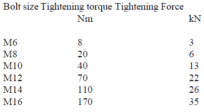
l) Correctness of sizes and terminations. Torque tables shall be followed.
m) Cable entry/tray provisions, top and bottom
n) Ventilation, anti-condensation heaters, and fans
o) Sealing/pad locking for meter cabinet
p) Phase barriers for incoming and outgoing breakers
q) Size of bus bars – neutral/earth
r) Gland plates
s) Color codes for cables
t) Ferrules, labels etc.
u) Termination of ECCs with copper lugs
v) Wiring connections of CT meter – load side of incomer
w) Mounting height of Meter, max 2M min 0.8M
Dielectric Tests Requirement (excluding components, lamps etc.)
All control fuses and electronic components shall be isolated. Test voltage of 2.5kV for 1 minute shall be applied between:
Phase to phase
Phase to neutral
Phase to earth
Neutral to earth
Protective Measures check/Electrical continuity of protective circuits
Capacity and continuity between:
a) All metal parts and main earth bar
b) Door and main earth bar
c) Continuity test according to control circuit diagram
d) Checking of indicator lamps (with transformers), voltmeter etc.
e) Outgoing circuits check with hand lamp.
Visual / Physical Checks
Check general arrangements of the components, internal wiring and complete cleanliness.
Check the panel against approved shop drawing to ensure that right components (ACB, MCCB) of correct ratings are installed.
Check the tray riser, cable drops cable overlapping and dressing of cable to MDB.
Check all the bolts / nuts and bus bar connection to ensure that all are in good and tight condition.
Check earth bonding of components and other related connection.
Check all meters and selector switches to ensure the correct selection & rating.
Check the phase barriers are properly fixed for separation of circuits.
Check all cables and panels are properly labelled and identified.
Insulation Resistance Check
Check and measure insulation resistance between phases, neutral and earth with 500 volts megger (the values to be verified with the permissible limits). Check the terminal insulation. cable gland termination and shrouding.
Functional Test (Panel to be temporarily energized)
- Check the control circuit of each system for its correct operation.
- Switch ON and OFF of all MCCBs, contactors, relays to verify for the desired operation.
- Check draw out mechanism of main incomer ACB.
- Check operation of the indication lamps & meters to ensure proper functioning.
- Check functions of motor operated ACB/MCCBs
- Check for any abnormal rise in temperature on bus bars. jumper cables, terminals and various devices by using an infrared scanner.
Earth Leakage Testing
a. Check earth leakage circuit breakers by means of RCCB tester, selecting 50% 100%, 150% of the rated sensitivity currents and the respective trip time to be recorded.
b. Check the rating of core balance CTS and EL relays for earth leakage protection.
c. Tabulate the readings taken.
Earth Fault Loop Impedance Test
Measure the earth loop impedance across phase and protective conductor with earth loop impedance
tester.
Tabulate the reading taken and check with permissible values.
Polarity Test
Check the polarity of incomer supply by polarity tester before energizing panels. Check all fuses/circuit breakers and single pole control devices are connected to phase conductors only.
Test on Capacitor Panels
a) Check the operation and indications of contactors in manual mode.
b) Check the operation and indications of contactors in auto mode by setting various power factor in the regulators.
Overall Performance Test – Check and ensure the satisfactory operation of the boards at full load.
