
In order to understand the usage of different types of capacitors in transmission lines we must first look in different way first the effect of power factor on the power system. Because the subject is related to the power factor correction. The power factor formula of an AC electric power system clearly indicates that this parameter is in fact the relation between the real power and the apparent power.
Power factor = 𝑟𝑒𝑎𝑙 𝑝𝑜𝑤𝑒𝑟 / 𝑎𝑝𝑝𝑎𝑟𝑒𝑛𝑡 𝑝𝑜𝑤𝑒𝑟
Real power is the capacity of the circuit for performing work in a particular time.
Apparent power is the product of the current and voltage of the circuit.
The apparent power in a system can be greater than the real power due to the following reasons;
- Energy stored in the load and returned to the source
- A non-linear load that distorts the wave shape of the current drawn from the source.
What Power Factor Value Indicates
Therefore, the power-factor of any system typically takes a value between 0 and 1. When the power factor is 1, all the energy supplied by the source is consumed by the load. But when the power factor is less than 1, part of the energy supplied by the source is stored and returned back to the source. In this situation inductive loads will absorb part of the energy supplied by the source and store it in its magnetic field, and capacitive loads will store it in its electric field.
Therefore, when the power factor is less than 1, more current is required to deliver the same amount of useful energy. Low power factor loads increase losses in the power distribution system and result in increased energy costs.
In order to minimize the electricity distribution line losses electric utility providers require that industrial and commercial customers maintain the power factors of their respective loads within specified limits. Otherwise they are subject to pay the additional charges. They also must maintain a high power factor on their distribution system for efficiency. Companies will typically bill customers for a low power factor or may be on kVA demand, which is also affected by power factor.
Most utility provider that bill a power factor penalty require a user to maintain a 95% Power Factor to avoid penalty. It is often possible to adjust the power factor of a system to very near unity. This practice is known as power factor correction and is achieved by switching in or out banks of inductors or capacitor banks.
Shunt Capacitors in Improving Power Factor of Load
Inductive components of a power system draw a lagging reactive power from the supply. It lags by 90o to the active power. The capacitive component of the power system leads by 90o to the active power. The directions of the above two components oppose each other.
Whenever an inductive load is connected to the transmission line, power-factor lags because of lagging load current. To compensate, a shunt capacitor is connected which draws current leading the source voltage. The net result is improvement in power factor.
Consider a load with a lagging power factor cosϕ1. This will consume an active power P1 and a reactive power Q1 as shown in the figure.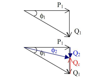
If the power factor is to be improved to a new value, cosϕ2, greater than cosϕ1, then a certain amount of leading reactive power Qc must be added. This is usually done by the use of shunt capacitors.
ϕ2 < ϕ1
cosϕ2 > cosϕ1
In this case the power factor has improved by adding shunt capacitors.
The effects of series and shunt capacitance
Series Connection of Capacitors
This is not a very common method of connecting capacitors. In this method, the voltage regulation is high, but it has many disadvantages. Because of the series connection, in a short circuit condition the capacitor should be able to
withstand the high current. Due to the series connection and the inductivity of the line there can be a resonance occurring at a certain capacitive value. This will lead to very low impedance and may cause very high currents to flow through the lines.
Shunt Capacitor Connection
This is the most common method of connection. . The capacitor is connected in parallel to the unit. The voltage rating of the capacitor is usually the same as or a little higher than the system voltage.
Alternate Power Factor Improvement Methods
There are other methods as well that are very useful in order to improve the power factor of transmission lines. These include use of synchronous motors and filters.
Synchronous Motor
An unloaded synchronous motor can be used to improve the powerfactor. It is started and connected to the electrical network. It operates at full leading power factor and puts apparent power onto the network as required to support a system’s voltage or to maintain the system power factor at a specified level. The condenser’s installation and operation are identical to large electric motors. Its principal advantage is the ease with which the amount of correction can be adjusted; it behaves like an electrically variable capacitor.
Harmonic Filters
If there are harmonics in the waveform caused by switched mode power supplies, the capacitors are not connected directly to the supply lines. The simplest way to control the harmonic current is to use a filter. It is possible to design a filter that passes current only at line frequency (e.g. 50 or 60 Hz). This filter removes the harmonic current, which means that the non-linear device now looks like a linear load. At this point the power factor can be brought to near unity, using capacitors or inductors as required. This filter requires large-value high-current inductors, however, which are bulky and expensive.
Power Factor Calculation
Calculation of series and shunt capacitance are done in the same method.
When capacitor is connected in series;
Per Unit compensation of the line = Series Capacitive Reactance / Inductive Reactance
= (1 / jωC) x ( 1 / jωL) = (1 / j × 2πf ×C) x ( 1 / j × 2πf ×L) = 1 / ( j2 × 4π2 f2 × CL)
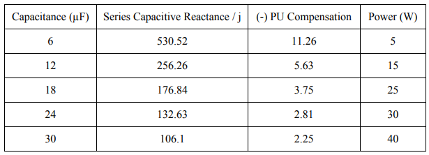
E.g. At C = 12 µF and at L = 0.15 H;
Series capacitive reactance = 1 / jωC = 1 / j × 2π × 50 × 12 × 10−6 Ω = -j265.26 Ω
Per unit compensation of the line = 1 / −1 × 4π2 × 502 × 12 × 10-6 × 0.15 = -5.63
When capacitor is connected in shunt;
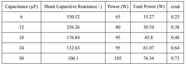
Total Power = V2 / R = V2 / (1/ωC) = V2 ωC
P = V2 ωC = Wcosϕ
Power Factor, cosϕ = V2ωC / W
Where W is the Wattmeter reading
E.g. At C = 12 µF, W = 80 W and V = 90 V,
Power Factor, cosϕ = 902 × 2𝜋 × 50 × 12 × 10-6 / 80 = 0.38
Sharing is caring:

Discover more from Electrical Engineering 123
Subscribe to get the latest posts sent to your email.