
What is a Digital Multimeter?
Digital Multimeter also famous as DMM is simply an electronic instrument that measures electrical parameters including AC/DC volts, AC/DC current, resistance. In addition digital multimeter may have a variety of special features that are designed for a wide number of applications like frequency, temperature, capacitance and continuity in a circuit.
Multimeter is most common & important laboratory measuring instrument. On the other hand for any electrician as well it is basic device which he must understand and use properly. It gives digital output, which is very accurate as compared to analogue meters. As the name suggests, multimeter are those measuring instruments or electrical devices which can be used to calculate multiple circuit characteristics.
Parts of Digital Multimeter
A multimeter has three major parts i.e. display, selection knob and ports. Two probes are plugged into two of the ports on the front of the unit. COM stands for common and is almost always connected to Ground or ‘-’ of a circuit.
10A is the special port used when measuring large currents (greater than 200mA). mAVΩ is the port that the red probe is conventionally plugged in to. This port allows the measurement of current (up to 200mA), voltage (V), and resistance (Ω).
Some multimeter employ the rotary switch to handle the switching ON and OFF options while some require a slider switch. The selection knob allows the user to set the multimeter to read different things such as milliamps (mA) of current, voltage (V) and resistance (Ω).
The LCD is embedded on the PCB and is interfaced through pin-outs on the PCB itself. A transparent plastic casing is over the LCD protecting it from the scratches. Also, shock absorption is provided by the rubber pads closely attached at the top and bottom of the LCD.
The display usually has four digits and the ability to display a negative sign as well. Some of the multimeter have illuminated displays for better viewing in low light situations.
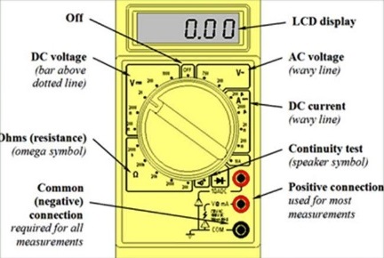
Understanding the Front Panel of Digital Multimeter
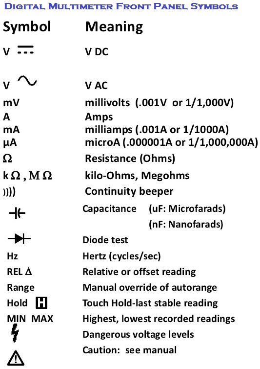
The front panel of most of the DMM contains basic symbols and indications, below is full detail of the symbols and components which are of most concern for any user or electricians.
Understanding DMM Display Specs
Display is specified as Digits or as Count
Digits: 3 1/2, 4 1/2, etc.
Example: 3 1/2: (read as three and half digit DMM)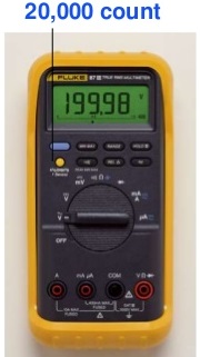
– starting from the least significant digit (right most), 3 “full” digits from 0-9
– Left most digit – 1 “half” digit (can read less than 9). Ex: 1999
Count: 3200, 4000, etc…
– 4000 count display reads from 0-3999 – 3200 count display reads from 0-3199
Accuracy is specified in percentage %
Closeness with which an instrument reading approaches the true value being measured; or largest allowable error.
Percentage of reading (digital multi-meters) vs. percentage of scale or range (analog meters):
Example: 1% scale vs. 1% reading %
scale: If scale or range is 1000V, an accuracy of 1% is equal to +/- 10V. 120V reading could = 110-130V.
% reading: 1% accuracy with 120V reading= 118.8-121.2V.
Least significant digit unstable:
Example: Accuracy spec = +/-(1%+2)
Reading of 200.0mV= 197.8 – 202.2mV
Range and Resolution
Resolution is the smallest change in measured value to which the instrument will respond.
As the range increases, the resolution decreases. For maximum resolution, choose the lowest possible range.
|
Range |
Resolution |
|
400.0mV |
0.1mV (=1/10 mV) |
|
4.000V |
.001V (=1mV) |
|
40.00V |
.01V (=10mV) |
|
400.0V |
0.1V (=100mV) |
|
1000V |
1V (=1000mV) |
Measurements using Multimeter
Measuring voltage:
Testing for proper supply voltage is usually the first step when troubleshooting a circuit. Below are steps on how to make voltage measurements:
- Select V~ (ac) or V (dc), as desired.
- Plug the black test probe into the COM input jack. Plug the red test probe into the V input jack.
- If the DMM has manual ranging only, select the highest range so as not to overload the input.
- Touch the probe tips to the circuit across a load or power source (in parallel to the circuit).
- View the reading, being sure to note the unit of measurement.
Resistance Measurement
Most DMMs measure down to 0.1Ω, and some measure as high as 300 MΩ (300,000,000 ohms). Infinite resistance (open circuit) is read as“OL” on the meter display. Below are the steps on how to make resistance measurements.
- Turn off power to the circuit.
- Select resistance (Ω).
- Plug the black test probe into the COM input jack. Plug the red test probe into the Ω input jack.
- Connect the probe tips across the component or portion of the circuit for which you want to determine resistance.
- View the reading, being sure to note the unit of measurement– ohms (Ω), kilo-ohms(kΩ), or mega-ohms (MΩ).
Measuring the DC and AC current
Current measurements taken with the DMM alone require placing the meter in series with the circuit being measured. This means opening the circuit and using the DMM test leads to complete the circuit. Below are the steps on how to make current measurements using digital multimeter.
- Turn off power to the circuit.
- Cut or unsolder the circuit, creating a place where the meter probes can be inserted.
- Select A~ (ac) or A (dc) as desired.
- Plug the black test probe into the COM input jack. Plug the red test probe into the amp or milliamp input jack, depending on the expected value of the reading.
- Connect the probe tips to the circuit across the break so that all current will flow through the DMM (a series connection).
- Turn the circuit power back on.
- View the reading, being sure to note the unit of measurement.
What does “rms” mean in Multimeter
True-rms vs. Average-sensing
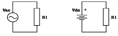
RMS is the Root Mean Square or effective heating value of any ac voltage or current waveform. RMS is the equivalent DC heating value of an AC waveform. Power consumed in R1 is same for both AC and DC source if the VacRMS = Vdc.
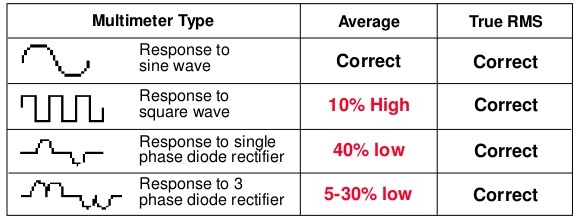
Average-sensing works for a perfect sinewave. An average-sensing meter assumes a non-distorted sine wave and does the following calculation:
RMS value = 1.11 X Average value
What if the waveform is non-sinusoidal?
For this current waveform, the effective or True-rms value = 1.85 x Average value.
An average-sensing meter’s reading (1.11 x Average) would be 40 % too low.
Average-sensing meters typically measure RMS high for voltage and low for current where there is waveform distortion. True-rms meter or clamp accurately measures both distorted waveforms and sine waves.
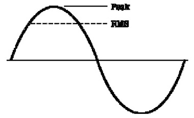
What is Crest Factor?
Crest Factor = Peak / RMS
For ideal sine wave, CF = 1.414
For below current waveform, Crest Factor = 2.917
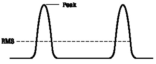
Crest Factor is an indication of harmonics. For current measurement, the higher the CF, the greater the waveform distortion. CF spec is important for current clamp, since current distortion is typically higher than voltage distortion.
Why Choose Fluke Multimeter?
Fluke designs its DMMs to the latest, most demanding safety standards. Fluke offers many DMMs with different combinations of features like Touch Hold, analog bar graphs, and enhanced resolution. Accessories for high current and temperature measurements are available to extend the capabilities of fluke multimeter.
