
Direct current or DC machines are used for the conversion of one form of energy to another. Similarly a DC Generator is used to generate the energy which works on the principle of converting mechanical energy into electrical energy. Basic law or principle behind the generator is the Faraday’s law of electromagnetic induction which states that whenever a conductor is moved in the magnetic field such that it cuts across the lines of flux, dynamically induced electromagnetic force emf is produced. The magnitude of this induced e.m.f in the conductor is given by the equation:
e = Blv sin θ Where
l = length of the portion of the conductor within the magnetic field
v = velocity of the conductor
B = magnetic flux density
θ = angle between direction of movement of the conductor and the direction of magnetic flux.
The following diagram explains the principle operation of dc generator.
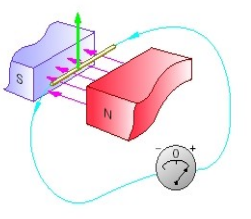
Principle of DC Generator
A DC generator produces direct power based on fundamental principle of Faraday’s laws of electromagnetic induction. According to these laws, when a conductor moves in a magnetic field it cuts magnetic lines force, due to which an e.m.f is induced in the conductor. The magnitude of this induced e.m.f depends upon the rate of change of flux (magnetic line force) linkage with the conductor. This electromotive force emf will cause current to flow if the conductor circuit is closed. Hence the two essential parts of a generator are a magnetic field and conductors which move inside that magnetic field.
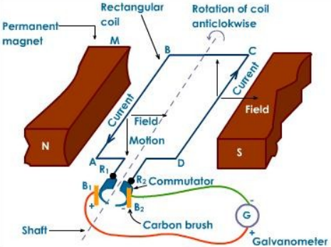
Let’s understand the basic principle of DC generator from above figure that shows a single loop of conductor of rectangular shape is placed between two opposite poles of magnet. Now consider rectangular loop of conductor is ABCD which rotates inside the magnetic field about its own axis ab. When the loop rotates from its vertical position to its horizontal position, it cuts the flux lines of the field. During the movement two sides, i.e. AB and CD of the loop cut the flux lines there will be an e.m.f induced in both sides (AB & DC) of the loop. As the loop is closed there will be a current circulating through the loop. The direction of the current can be determined by Fleming’s right hand Rule. The waveform of the current through the load circuit is as shown in the below figure. This current is unidirectional.
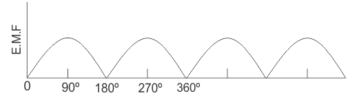
waveform-of-the-current-from-dc-generator
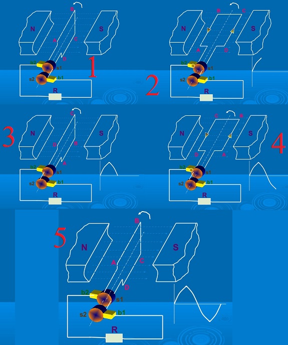
Consider a single turn rectangular copper coil is rotating in a magnetic field. The coil occupies different angular positions during its rotation. When the coil is rotated through an angle of 90° the emf induced in the coil is maximum. Rotate the coil further by an angle of 180° the emf induced in the coil will be zero. Rotate the coil further by an angle of 270° the emf induced in the coil is maximum in the reverse direction. We conclude that the nature of the emf induced is actually alternating.
Construction of DC Generator
A DC Generator has the following parts:
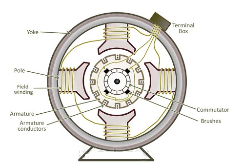
- Yoke
- Rotor
- Stator
- Field winding
- Field electromagnets
- Pole core and pole shoe
- shaft
- Coil
- Armature of dc generator
- Commutator of DC Generator
- Brushes of generator
- Bearing
Yoke of DC Generator
It holds the magnetic pole cores of the generator and acts as cover of the generator. It carries the magnetic field flux. In small generator, yoke are made of cast iron but for large construction of DC generator, where weight of the machine is concerned, lighter cast steel or rolled steel is preferable for constructing yoke of dc generator.
Pole cores and pole shoes of DC Generator
There are mainly two types of construction available:
- Solid pole core, where it made of a solid single piece of cast iron or cast steel.
- Laminated pole core, where it made of numbers of thin, plates of annealed steel. The construction of magnetic poles basically comprises of two parts namely, the pole core and the pole shoe, stacked together and then attached to the yoke.
Above mentioned two structures are assigned for different purposes, the pole core is of small cross sectional area and its function is to just hold the pole shoe over the yoke, whereas the pole shoe having a relatively larger cross-sectional area spreads the flux produced over the air gap Pole cores and pole shoes of DC Generator.
Armature Core of DC Generator
The purpose of armature core is to hold the armature winding and provide low reluctance path for the flux. Although a dc generator provides direct current but induced current in the armature is alternating in nature. That is why, cylindrical or drum shaped armature core is build up of circular laminated sheet. In every circular lamination, slots are either die – cut or punched on the outer periphery and the key way is located on the inner periphery.
Armature Winding of DC Generator
Armature winding are generally formed wound. Various conductors of the coils are insulated from each other. The conductors are placed in the armature slots, which are lined with tough insulating material.
Armature windings can be divided into two groups, depending upon the manner in which the wires are joined to the commutator, namely:
- Lap windings
- Wave windings
In lap windings the two ends of any one coil are taken to adjacent segments. In wave windings the two ends of each coil are bent in opposite directions and taken to segments some distance apart. If a dc generating machine has p pairs of poles, No. of parallel paths with a lap winding = 2p and No. of parallel paths with a wave winding = 2.
Commutator of DC Generator
The commutator plays a vital role in dc generator. It collects current from armature and sends it to the load as direct current. It actually takes alternating current from armature and converts it to direct current and then send it to external load. It is cylindrical structured and is build up of wedge – shaped segments of high conductivity, hard drawn or drop forged copper. Each segment is insulated from the shaft.
Brushes of DC Generator
The brushes are made of carbon. These are rectangular block shaped. Only function of these carbon brushes of dc generator is to collect current from commutator segments. The brushes are housed in the rectangular box shaped brush holder.
Classification of DC Generators
DC generators can be classified mainly in two classes i.e. separately excited and self excited. Further self excited generators are classified in Shunt generator, Series generator, Compound generator, Long shunt compound and short shunt compound generators.
In separately excited DC Generators the field winding is excited by a separate source of d.c current. The field current can be varied by a variable resistance connected in series. In shunt Generator field winding is connected in parallel to armature. In series generator field winding is connected in series with armature. In a long Shunt Compound Generator Both series and shunt windings are present. In short Shunt Compound Generator the shunt field is connected across the armature terminals only.
There are many generac generators which are used for different purposes and known with different terms in a common man’s language depending upon their usage and brand names like portable generator, diesel generator, permanent magnet generator, generater, dg set, portable diesel generator, gas generator,natural gas generator, standby generator, solar power generator, electric generator, power generator, yamaha generator, kohler generators, propane generator.
