
What is the Wheatstone Bridge?
The Wheatstone Bridge consists of a dc voltage source, four resistors and a detector. The detector is a type of ammeter called a galvanometer. The galvanometer is used to detect the condition ig = 0 .When the circuit satisfies this condition we say that “the bridge is balanced”.
A Wheatstone bridge is an electrical circuit used to measure an unknown electrical resistance by balancing two legs of abridge circuit, one leg of which includes the unknown component. The primary benefit of a wheatstone bridge is its ability to provide extremely accurate measurements (in contrast with something like a simple voltage divider). Its operation is similar to the original potentiometer.
The Wheatstone bridge was invented by Samuel Hunter Christie in 1833 and improved and popularized by Sir Charles Wheatstone in 1843. One of the Wheatstone bridge’s initial uses was for the purpose of soils analysis and comparison.
wheatstone bridge theory
The Whitestone bridge is the fundamental bridge, but there are other modifications that can be made to measure various kinds of resistances when the fundamental Wheatstone bridge is not suitable. Some of the modifications are:
- Carey Foster bridge, for measuring small resistances
- Kelvin bridge, for measuring small four-terminal resistances
- Maxwell bridge, for measuring reactive components
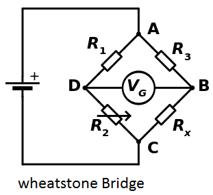
In the figure, 


Detecting zero current with a galvanometer can be done to extremely high accuracy. Therefore, if
At the point of balance, the ratio of
![{\displaystyle {\begin{aligned}{\frac {R_{2}}{R_{1}}}&={\frac {R_{x}}{R_{3}}}\\[4pt]\Rightarrow R_{x}&={\frac {R_{2}}{R_{1}}}\cdot R_{3}\end{aligned}}}](https://wikimedia.org/api/rest_v1/media/math/render/svg/1d10637c0ae2c1ef7ee40aa0d5f8cce2108367b7)
Alternatively, if
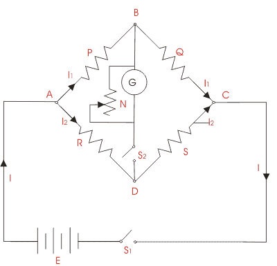 Let’s understand the use of Wheatstone bridge theory by below given experiment. The objective of the experience is to find the value of resistance of a given resistor using a Wheatstone bridge. The general arrangement of Wheatstone bridge circuit is shown in the figure below. It is a four arms bridge circuit where arm AB, BC, CD and AD are consisting of electrical resistances P, Q, S and R respectively. Among these resistances P and Q are known fixed electrical resistances and these two arms are referred as ratio arms. An accurate and sensitive Galvanometer is connected between the terminals B and D through a switch S2. Refer to whitestone bridge diagram, the voltage source of this Wheatstone bridge is connected to the terminals A and C via a switch S1 as shown. A variable resistor S is connected between point C and D. The potential at point D can be varied by adjusting the value of variable resistor. Suppose current I1 and current I2 are flowing through the paths ABC and ADC respectively. If we vary the electrical resistance value of arm CD the value of current I2 will also be varied as the voltage across A and C is fixed. If we continue to adjust the variable resistance one situation may comes when voltage drop across the resistor S that is I2.S becomes exactly equal to voltage drop across resistor Q that is I1.Q. Thus the potential at point B becomes equal to the potential at point D hence potential difference between these two points is zero hence current through galvanometer is nil. Then the deflection in the galvanometer is nil when the switch S2 is closed. Theoretically, we have the equation for the circuit as (P/R) = (Q/S).
Experiment Procedure:
- Circuit in the module is setup as given in the figure.
- Resistance value of P, Q and R are set as 10 kilo ohms.
- Power supply of 15 V is given at point A and point C is grounded.
- Resistor, S is varied accordingly to get zero current in the galvanometer.
Value of resistor S is noted down for the zero current through the galvanometer which comes out to be around 9.71 kilo ohms that theoretically should be 10 kilo ohms. The difference in the value can be attributed to internal resistance of the power supply, resistance of connecting wires and/or insufficient sensitivity of the galvanometer.
