
What is a VFD?
As the name describes VFD or Variable Frequency Drive is motor controller that drives an electric motor by applying the varying frequency and voltage to the electric motor that are used in the case where we need to change the speed of motors depending upon the load requirements. Other names for a VFD are variable speed drive, adjustable speed drive, adjustable frequency drive, or an AC drive. It should be understood that the frequency or hertz fed to the motor are directly related to the motor’s speed which is measured in RPMs i.e. revolutions per minute.
VFD Principle
Now let’s understand what principle is applied to vary the frequency in VFD. Variable Frequency Drive also termed as AC inverter or electronic speed controller for AC motors converts the AC supply to DC using a rectifier / diode, then converts it back to a variable frequency by using a inverter bridge. Standard motors are constant speed and when they are energized they run at a 100% speed no matter whatever is the required load. VFD is mainly required when we need to change the speed of motor i.e. fans and HVAC system equipment’s like air handling units and chilled water pumps etc that are subject to use of variable speed electric motor.
Equation of vfd motor speed
Speed= 120 x f /P
P=No. of poles
F=Line Frequency
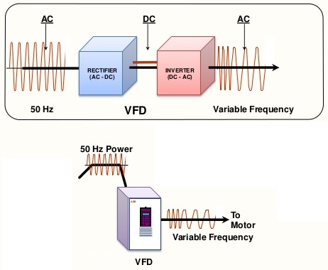
VFD Block Diagram
Sequence of operation for VFD Variable Frequency Drive
- First of all the Converter (usually a diode rectifier) converts three-phase AC power to DC power.
- Next, the DC Bus stores and filters the DC power in a large bank of capacitors.
- At last, the Inverter (usually a set of six IGBTs) switches or inverts the DC power in a Pulse Width Modulated (PWM) AC waveform to the motor.
Variable Frequency Drive VFD Control Modes
Scalar Control Mode: In this control mode the frequency drive is unaware of what is happening on the motor side. For example A 400V scalar drive is told to run a 400V, 50 Hz motor at 50% speed Following V/F pattern, Voltage applied by the drive will also be half and this is perfect when there is no load. But after loading, motor will run at less than 50% speed so the VF drive is unaware of the status of motor.
 Vector Control Mode: Opposite to scalar control mode this mode is aware of what is happening on the motor side. Vector control is implemented using the sensor on the motor side. The benefits of vector control mode include feedback through encoder, better speed regulations up to 0.01% and faster response to load variations.
VFD controllers require lots of settings and adjustment, some of the input Parameters include:
- Max./Base frequency setting
- Motor rated output
- Motor rated voltage
- Motor rated current.
There are different Frequency Reference setting methods:
- Stop Command method
- Start frequency
- Stop frequency (DC Braking starts)
- Torque Boost methods.
Frequency Reference Setting Methods include:
- Potentiometer
- 0-10V input voltage
- 4-20(mA)
Sharing is caring:

Discover more from Electrical Engineering 123
Subscribe to get the latest posts sent to your email.
Pingback: Critical Site Electrical Testing Requirements for Electrical Contractors