
Optical fiber cable is the most important subject for large data and voice communication. Obviously like all other communication system, the primary objective of optical fiber communication system is to transfer successfully the signal containing information (voice, data, video) from the source to the destination without any or minimal data losses.
Since the signals in FO cable travel in the form of light therefore we can term the losses in fiber optic cables as light losses or optical losses.
In order to connect an optical fiber cable to intermediate equipment’s and devices special connectors are useful that include SC connectors and ST connectors. In order to achieve best results the quality of joints with connectors and from fiber to fiber is very critical. Therefore this page much talks about the jointing of optical fiber cable.
In order to understand the importance of optic hair jointing which is termed as splicing lets first have a look on the general block diagram of optical fiber communication system as shown in the figure below.
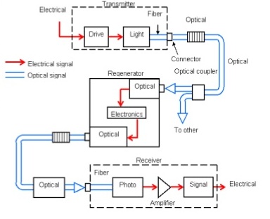
As you can see there are many steps involved in communication of optical data and most important after optical cable itself are transmitters and receivers. But if data is lost or distorted what receiver will do, obviously it can not recover the data loss. Therefore here we shall understand the procedure of good quality fiber optik installation part which is splicing or jointing. After that we shall see how the data loss or installation quality is measured.
Typically or we can say still more common method of joining optical fibers is termination or connectorization but splicing is becoming more and more famous and reliable jointing method for fiber optic cables.
What is Splicing of Optical Fiber Cable
Fiber optic splicing involves joining two fiber optic cables together in order to avoid the light losses. Fiber splicing typically results in lower light loss and back reflection than termination making it the preferred method when the cable runs are too long for a single length of fiber or when joining two different types of cable together, such as a 48-fiber cable to four 12-fiber cables.
Method of Fiber Optic Splicing
There are two methods of fiber optic splicing i.e. fusion splicing and mechanical splicing which we shall see in detail in the following sections.
Fusion Splicing
Fusion splicing is the process of fusing or welding two fibers together usually by an electric arc. This method is the most widely used method of splicing the FO cables since it provides for the lowest loss and least reflectance. In addition the fusion splicing provides the strongest and most reliable joint between two fibers.
It is possible to splice one fiber at a time or a complete fiber ribbon from ribbon cable at one time. First we shall understand single fiber splicing and then ribbon splicing.
Fusion splicing machines are mostly automated tools that require you pre-set the splicing parameters or choose factory recommended settings that will control the splicing process itself.
Steps involved in fusion splicing of Optical Fiber
Stripping: First of all the remove the jacket and cladding of two fibre optik ends which are to be joined, using the special tool i.e. Stripper.
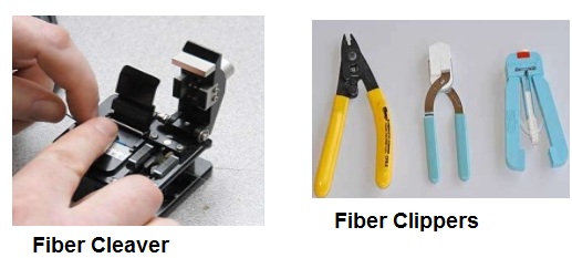
Cleaving: After stripping the cladding, the glass core is cleaned with ethyl alcohol. Now, for an efficient splicing it is necessary that both ends are at 90 degree finish. For this, a special precision diamond cutter is useful, which we call Cleaver. Most of the time cleaver is coming with the splicing machines. A precision fiber cleaver that scribes and breaks (cleaves) the fibers precisely is very critical for splicing results, because the quality of the splice will depend on the quality of the cleave.
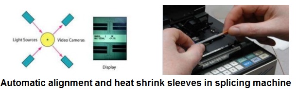
Fusing the fiber: This stage further needs two activities. The first is the alignment and after that heating or fusing the fiber. The alignment is also automatic process done by the splicing tool itself. In the process of alignment ends of the optical fibers are on moveable stages which are usable to align the fibers and set the end gap automatically.
After alignment is perfect the heating process follows through an electric arc within the splicer and then two fibres become joined like a single one. After the fusion is complete, mostly splicing machines are putting heat shrinking protective sleeve over the splice to protect it from moisture or other environmental hazards.
Optical Fiber Mechanical Splicing
In mechanical splicing method a self-contained assembly aligns and holds the fibers in right place instead of a permanent bond. Mechanical splicing technique aligns the two fiber ends to a common centre line, aligning their cores so the light can pass from one fiber to another. There are four steps in performing a mechanical splice.
Step 1 – Preparing the fiber: Strip the protective coatings, jackets, tubes, strength members, etc. leaving only the bare fiber showing. The main concern here is cleanliness.
Step 2 – Cleave the fiber: The process is identical to the cleaving for fusion splicing but the cleave precision is not as critical in comparison to this method.
Step 3- Mechanically join the fibers: There is no heat used in this method. Simply position the fiber ends together inside the mechanical splice unit. The index matching gel inside the mechanical splice apparatus will help couple the light from one fiber end to the other. Older apparatus will have an epoxy rather than the index matching gel holding the cores together.
Step 4 – Protect the fiber: In this method mechanical splice provides its own protection for the splice.
Below table summarizes the difference between fusion and mechanical splicing.
| S.# | Fusion Splicing | Mechanical Splicing |
| 1. | Two fiber ends are aligned and then fused together. | Just a mechanical alignment device. |
| 2. | Fused with the help of electric arc. | Splice with the help of index matching gel. |
| 3. | Still, two separated fibres are not continuous. | The joint is continuous. |
| 4. | Due to electric arc, the strength of glass core weakens at the point of splicing, which causes losses. | No such problem is encountered in mechanical splicing. |
Attenuation or Power Losses in Optical Fiber
Attenuation or loss in optical fibers basically refers to the loss of power. During transit, light pulse loses some of their photons, thus reducing their amplitude. Attenuation for a fiber is usually specified in decibels per kilometre. The degree of attenuation depends on the wavelength of light transmitted during optical fiber communications.
Types of FO Power Losses
Material absorption losses: These losses are related to materials quality, composition and fabrication process of the fiber which results in the dissipation of some of the transmitted optical power as heat in wave guide. The absorption of light may be intrinsic (caused by one or more major components of glass) or extrinsic (caused by impurities within the glass).
Linear scattering losses: Linear scattering mechanism causes the transfer of some or all of the optical power contained within one propagating mode to be transferred linearly (proportionally) into a different mode. This process tends to result in attenuation of the transmitted light as the transfer may be to a leaky or radiation mode which does not continue to propagate within the fiber core, but is radiated from the fiber. It is mainly of two types i.e. Rayleigh scattering and Mie scattering
Bending loss: Radiative losses occur whenever an optical fiber undergoes a bend of finite radius of curvature.
Measurement of Fiber Optic Attenuation or Power Losses
The most basic fiber optic measurement is optical power from the end of a fiber. This measurement is the basis for loss measurements as well as the power from a source or presented at a receiver. Measurement of the power of a transmitter is done by attaching a test cable to the source and measuring the power at the other end. For receivers, one disconnects the cable attached to the receiver receptacle and measures the output with the meter.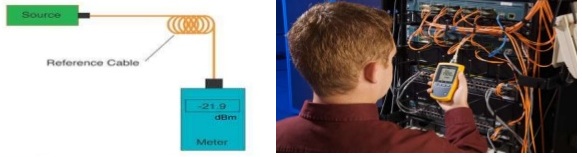
Optical power meters typically use semiconductor detectors since they are sensitive to light in the wavelengths and power levels common to fiber optics. Most fiber optic power meters are available with a choice of 3 different detectors, silicon (Si), Germanium (Ge), or Indium-Gallium-Arsenide (In GaAs).
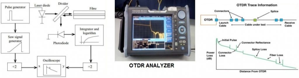
The second method for optical fiber system testing is the OTDR Measurement. OTDR stands for optical time domain reflectometry. The OTDR is the most important investigation tool for optical fibers, which is applicable for the measurement of fibre loss, connector loss and for the determination of the exact place and the value of cable discontinuities.
Principal of the OTDR Analyzer
A short light pulse is transmitted into the fibre under test and the time of the incidence and the amplitude of the reflected pulses are measured.
The resolution of the OTDR – the dead zone
The resolution of the OTDR system is the distance of two reflecting points that still can be distinguished by the instrument. This depends on the width of the transmitted impulse, since the impulse must not overlap.
