
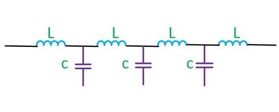
The parameters of a transmission line are Resistance (R), Inductance (L), Capacitance (C) and Conductance (G). Resistance (R) is defined as the loop resistance per unit length of the wire. Its unit is ohm/Km. Inductance (L) is defined as the loop inductance per unit length of the wire. Its unit is Henry/Km. Capacitance (C) is defined as the loop capacitance per unit length of the wire. Its unit is Farad/Km. Conductance (G) is defined as the loop conductance per unit length of the wire. Its unit is mho/Km.
What are the secondary constants of a line? Why the line parameters are called distributed elements?
The secondary constants of a line are Characteristic Impedance and Propagation Constant. Since the line constants R, L, C, G are distributed through the entire length of the line, they are called as distributed elements. They are also called as primary constants.
Characteristic impedance of power transmission line
Characteristic impedance is the impedance measured at the sending end of the line. It is given by:
Z0 = Z/Y,
where
Z = R + jωL is the series impedance
Y = G + jωC is the shunt admittance
Propagation constant of Line
Propagation constant is defined as the natural logarithm of the ratio of the sending end current or voltage to the receiving end current or voltage of the line. It gives the manner in the wave is propagated along a line and specifies the variation of voltage and current in the line as a function of distance. Propagation constant is a complex quantity and is expressed as
γ = α + j β
The real part is called the attenuation constant α whereas the imaginary part of propagation constant is called the phase constant β
What is a finite and infinite line?
A finite line is a line having a finite length on the line. It is a line, which is terminated, in its characteristic impedance (ZR=Z0), so the input impedance of the finite power line is equal to the characteristic impedance (Zs=Z0).
An infinite line is a line in which the length of the transmission line is infinite. A finite line, which is terminated in its characteristic impedance, is termed as infinite line. So for an infinite line, the input impedance is equivalent to the characteristic impedance.
What is wavelength of a transmission line?
The distance the wave travels along the transmission line while the phase angle is changing through 2Π radians is called a wavelength.
Types of Line loading?
- Continuous loading
- Patch loading
- Lumped loading
Continuous loading: Continuous loading is the process of increasing the inductance value by placing a iron core or a magnetic tape over the conductor of the line.
Patch loading: It is the process of using sections of continuously loaded cables separated by sections of unloaded cables which increases the inductance value
Lumped loading: Lumped loading is the process of increasing the inductance value by placing lumped inductors at specific intervals along the line, which avoids the distortion
Define reflection coefficient and reflection loss
Reflection Coefficient can be defined as the ratio of the reflected voltage to the incident voltage at the receiving end of the line.
Reflection Coefficient K=Reflected Voltage at load /Incident voltage at the load
K=Vr/Vi
Reflection loss is defined as the number of nepers or decibels by which the current in the load under image matched conditions would exceed the current actually flowing in the load.
What is Impedance matching?
If the load impedance is not equal to the source impedance, then all the power that are transmitted from the source will not reach the load end and hence some power is wasted. This is called impedance mismatch condition. So for proper maximum power transfer, the impedance in the sending and receiving end are matched. This is called
impedance matching.
Insertion loss Definition
The insertion loss of a line or network is defined as the number of nepers or decibels by which the current in the load is changed by the insertion .
Insertion loss=Current flowing in the load without insertion of the network/Current flowing in the load with insertion of the network.
When reflection occurs in a line?
Reflection occurs because of the following cases:
- when the load end is open circuited
- when the load end is short-circuited
- when the line is not terminated in its characteristic impedance
When the line is either open or short circuited, then there is not resistance at the receiving end to absorb all the power transmitted from the source end. Hence all the power incident on the load gets completely reflected back to the source causing reflections in the line. When the line is terminated in its characteristic impedance, the load will absorb some power and some will be reflected back thus producing reflections.
What are the conditions for a perfect line? What is a smooth line?
For a perfect line, the resistance and the leakage conductance value were neglected. The conditions for a perfect line are R=G=0.
A smooth line is one in which the load is terminated by its characteristic impedance and no reflections occur in such a line. It is also called as flat line.
