
Gates are mainly the subject of digital logic designing profession which is a very basic and important section of digital world. In fact term logic is applied to digital circuits in order to implement the logic functions. There are many types of digital logic circuits which serve as the basis for designing a logic diagrams for a complex circuit, so we can say that logic gates are the basic elements that form the building blocks for such complex digital system as the computer. A circuit that performs a specific logic operation (AND, OR) is called a logic gate that are represented by the specific symbols and inputs and outputs are shown by lines. As a standard practice all the logic gate inputs are on the left of each symbol and the output is on the right side of the symbol. A logic gate is a digital circuit which either allows a signal to pass through it or to stop it. There are three basic logic gates i.e. AND, OR and NOT.
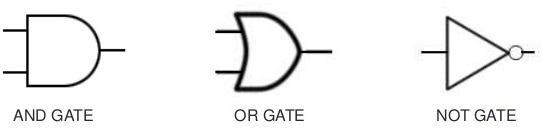
Basic Logic Gates
While understanding the logic gates we should also understand the inverter, which is a unique gate that also called NOT gate or circuit, that performs the operation called inversion or complementation. The NOT operation changes one logic level to the opposite logical level. When the input is Low, the output is high. When the input is high, the output is low. The inverter changes one logic level to the opposite level. In terms of bits, it changes a 1 to 0 and 0 to 1.
Truth Table for NOT Gate / Inverter
|
X (Input) |
Y (Output) |
|
0 |
1 |
| 1 |
0 |
The AND Gate
AND gate can have two or more inputs and performs what is know as multiplication. The output of AND gate is high when all inputs are high otherwise all outputs are low. Like if two inputs are 1,1 the output will be 1, in all other conditions output will be 0 i.e. for (1,0), (0,1) and (0,0). So to summarize the operation of AND gate we can say that AND gate produces a HIGH output only when all of the inputs are HIGH. When any of the inputs is LOW, the output is LOW. Therefore, the basic purpose of AND gate is to determine when certain conditions are simultaneously true, as indicated by High levels on all of its inputs, and produces a High on its output.
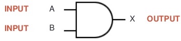
The output will be positive (true) when both inputs (the input one AND the input two) are positive (true).
AND Gate is presented by X = A . B
Example of implementation of AND Gate
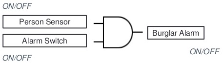
If both the Person Sensor AND the Alarm Switch are on then the Burglar Alarm is activated.
Truth Table for AND Gate
|
Inputs |
Output | |
|
A |
B | X |
|
0 |
0 |
0 |
|
0 |
1 |
0 |
|
1 |
0 |
0 |
| 1 | 1 |
1 |
THE OR GATE
OR gate can have two or more inputs and performs what is known as logical addition. The output of OR gate is Low when all inputs are low, otherwise all outputs are high means if any input is high or 1 the output will be high or 1 so we can say this is a simple addition process. An OR gate produces a High on the output when any of the inputs is High. The output is Low only when all of the inputs are Low. Therefore, an OR gate determines when one or more of its inputs are High and produces a High on its output.
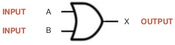
The output will be positive (True) if at least one input is true. X = A OR B
Example of OR Logic Gate Implementation:
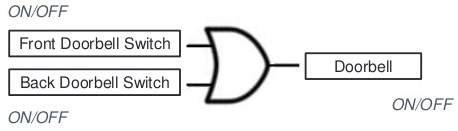
If either the Front Doorbell Switch OR the Back Doorbell Switch is pressed then the Doorbell rings.
Truth Table for OR Gate
X = A OR B
|
Inputs |
Output | |
|
A |
B | X |
|
0 |
0 |
0 |
|
0 |
1 |
1 |
|
1 |
0 |
1 |
| 1 | 1 |
1 |
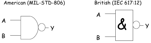
THE NAND GATE / UNIVERSAL GATE
The NAND gate is the one of the most popular and used logic element because it can be used as a universal gate. NAND gate can be used in combination to perform the AND, OR, and inverter operations. NAND Gate is constructed by attaching NOT Gate at the output of AND Gate, hence NAND Gate is called NOT- AND Gate. NAND Gate has two or more inputs and only one output. The output of NAND gate is low when all inputs are high, otherwise all outputs are high. NAND gate produces a Low output only when all the inputs are High. When any of the inputs is Low, the output will be High. You can see from below figure that first we applied AND operation to get W and then inverted the output to get the NAND output i.e. Z.
Truth Table for NAND Gate
|
Inputs |
Output | |
|
X |
Y | Z |
|
0 |
0 |
1 |
|
0 |
1 |
1 |
|
1 |
0 |
1 |
| 1 | 1 |
0 |
THE NOR GATE / UNIVERSAL GATE
The NOR gate is another example of universal gate that can be used for multiple logic operations. NOR gate is used in combination to perform the AND, OR and Inverter operations. NOR Gate is the combination of NOT gate at the output of OR gate, hence NOR gate is type of NOT-OR gate. NOR gate has two or more input and only one output. The Output of NOR gate is high when all inputs are low otherwise the output is low. A NOR gate produces a Low output when any of its inputs is high. Only when all of it’s inputs are low is the output high.
Truth Table for NOR Gate
|
Inputs |
Output | |
|
X |
Y | Z |
|
0 |
0 |
1 |
|
0 |
1 |
0 |
|
1 |
0 |
0 |
| 1 | 1 |
0 |
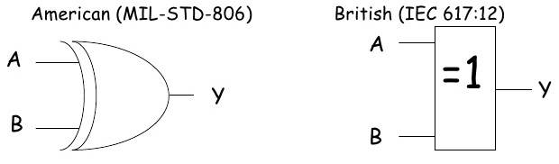
THE EXCLUSIVE EXOR GATE
The exclusive-OR gate has a graphical symbol similar to that of the OR gate, except for the additional curved line on the input side. It can take only 2 inputs. We can’t construct ExOR Gate using three input Ex-OR gate. If both inputs are Low or both are High then it produces the output Low or 0. otherwise it produce the High.
Exclusive OR EXOR Gate
Truth Table for Exclusive OR EXOR Gate
|
Inputs |
Output | |
|
X |
Y | Z |
|
0 |
0 |
0 |
|
0 |
1 |
1 |
|
1 |
0 |
1 |
| 1 | 1 |
0 |
EXCLUSIVE NOR EXNOR LOGIC GATE
The exclusive-NOR gate is the complement of the exclusive-OR gate, as indicated by small circle on the output side of the graphic symbol. It can take only 2 inputs. We can’t construct Ex-NOR Gate using three input EXOR gate. If both inputs are Low or both are High then it produces the output High or 1. otherwise it produce the Low output.
Truth Table for Exclusive NOR EXNOR Gate
|
Inputs |
Output | |
|
X |
Y | Z |
|
0 |
0 |
1 |
|
0 |
1 |
0 |
|
1 |
0 |
0 |
| 1 | 1 |
1 |
Sharing is caring:

Discover more from Electrical Engineering 123
Subscribe to get the latest posts to your email.