
Installation of small power system shall be carried out in accordance to Contract Specification and will be as per approved construction methodology, shop drawings and checklists.
Installation shall be carried out by skilled and suitably experienced electricians under supervision of highly competent site supervisors and engineers to be ensured the correctness and quality of installation.
Ensure that the location, type aid rating of socket outlets will be in accordance with technical specification, approved architectural plans and shop drawings.
Outlet boxes where mounted in walls will be located with the center line at elevation above the finished floor level (FFL), as specified on the shop drawings.
Reference datum line (FFL + 1 M) is marked by surveyor on the wall of each specific area. Identify, mark and locate concern G.I. back boxes as per approved shop drawings. Careful attention must be given to ensure that all the G.I. back boxes are mounted at the correct height from FFL as per approved shop drawings.
Back box for socket outlet in kitchen or other areas where water used must be positioned at least 1 meter away from source of water i.e. sinks, basins, filter units and supply taps etc.
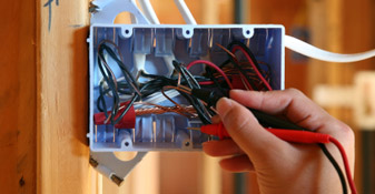
Containment works will be completed including connection of G.I. back boxes side by male adapter and lock nut.
Back to back installation of boxes will not be allowed in the gypsum wall. Only permitted is minimum 5cm distance between back to back boxes to be maintained.
Wiring will be pulled as per approved load schedule. Extra care must be given to identify the phase color, number and size of the wire.
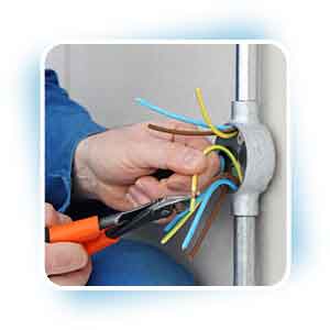
Earth wire shall be first terminated on the accessories and will loop to the back box earth stud. The back box depth shall be suited the requirements of the wiring accessories installed. Proper wire end termination will be maintained and neutral wiring will be provided for each circuit.
All wiring devices and switches will be installed levelled and plumb. All wiring devices will be install flush mounted on the wall. Switches shall be installed in such a way that toggle action is vertical and ON position at the bottom. All the wiring devices and switches shall be covered properly during installation to protect it from moisture, dust or other type of contaminants. Align accessories horizontally and vertically as indicated where accessories are grouped, mounted horizontally in line and parallel to each other and equidistant.
Boxes for similar equipment will be mounted in uniform heights. Bonding jumper (2.5 mm2 minimum) will be connected to socket earth terminal on flush mounted units. Weatherproof type socket outlet will be installed in all wet areas and shall be minimum rating of IP-55.
Floor outlets and floor boxes will be installed flush on the floor.
Where sockets are mounted vertically, the ground terminal shall be on the bottom, and where receptacles are mounted in the horizontal position, the ground terminal will be on the right position.
Tag/label will be provided for each wiring devices and switches as per approved tagging system
Proper access will be provided for operation and maintenance of sockets.
After the completion of installation, Inspection Request will be raised to the consultant to ensure high accuracy and quality of works.
Testing (insulation resistance, earth loop, impedance, polarity) will be carried out as per regulation and confirm the values are as per recommendations.
Sharing is caring:

Discover more from Electrical Engineering 123
Subscribe to get the latest posts to your email.