
Resistance definition & Meaning
Understanding of resistance is very basic requirement for electrical engineers or professionals, the question of resistance comes when we are talking about the conductors, metals, wires or cables etc. Electrical resistance in general is a measure of the difficulty to pass through electric current from any conductor. So in simple words we can say the ease of passing the current can be measured in terms of resistance i.e. if current is passing easily resistance is low and if current is passing in difficulty the resistance is high. Therefore now we come across another term which is opposite to resistance it is called electrical conductance from which the term conductor is also linked, so we can say that a good conductance means resistance is low and electric current passes very easily.
Ohm’s Law Of Resistance
If we talk about different materials they have different resistances and conductor with zero resistance is called super conductor. International unit of electrical resistance is the ohm (Ω), while electrical conductance is measured in siemens (S). The resistance which is denoted by R can be defined as the ratio of voltage across it V to current through it I, similarly the formula of conductance is the inverse denoted by G. Below are given the proportions among different parameters which are called Ohm’s Law of resistance & conductance. ohmic materials are defined which satisfy below definitions.

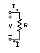
Ohm’s law is an empirical law relating the voltage V across an element to the current I through it:

As per Ohm’s law I is directly proportional to V which is not always true like it is false for diodes, batteries and other devices whose conductance is not constant. On the other hand we can say that this law is accurate for wires and resistors if we assume that other conditions, including temperature, are held constant.
How to Measure the Resistance
An instrument for measuring resistance is called an ohmmeter. Generally available simple ohmmeter devices are not able to measure low resistances accurately because their wires/leads also imply resistance which adds to the resistance of measured conductor causing a voltage drop that interferes with the measurement, so more accurate devices use four-terminal sensing.
| Component | Resistance (Ω) |
|---|---|
| 1 meter of copper wire with 1 mm diameter | 0.02 |
| 1 km overhead power line (typical) | 0.03 |
| AA battery (typical internal resistance) | 0.1 |
| Incandescent light bulb filament (typical) | 200–1000 |
| Human body | 1000 to 100,000 |
Relationship of Resistance, Reactance & Impedance
Now let’s discuss the relationship between electrical impedance and resistance. Electrical impedance describes a measure of opposition to alternating current (AC). Impedance can be thought of as the opposition of electrical current flow in a AC circuit. Electrical impedance extends the concept of resistance to AC circuits, describing not only the relative amplitudes of the voltage and current, but also the relative phases. In addition to Resistance, AC circuits also exhibit Reactance. Reactance is also the opposition to electrical current flow. By its very nature a DC circuit will not exhibit any form of Reactance, therefore opposition to current flow will always be measured in Resistance. Reactance exists in two forms, Capacitive & Inductive. the combination of Reactance & Resistance is called Impedance.
Any measurement of the opposition of current flow in an AC circuit will always be measured in Impedance. Impedance & Resistance are both measured in Ohms, and are interchangeable in many electrical formulas in practice i.e, Ohms Law.
When the circuit is driven with direct current (DC) there is no distinction between impedance and resistance, so in a DC circuit resistance is impedance with zero phase angle. The symbol for impedance is usually Z and it may be represented by writing its magnitude and phase in the form Z<θ. However, complex number representation is more powerful for circuit analysis purposes. The term impedance was coined by Oliver Heaviside in July 1886. Arthur Kennelly was the first to represent impedance with complex numbers in 1893.
Video Explanation of Electrical Resistance
Sharing is caring:

Discover more from Electrical Engineering 123
Subscribe to get the latest posts to your email.