Prior to commencement of diesel generator DG set installation work all shop drawing will be submitted for approval and approval will be obtained from the consulting engineer.
Approved shop drawing will show the routes with reference numbers as well as the supporting requirements. Only approved shop drawing will be used at the site for installation.
All materials to be used in this system will be submitted for Engineer’s approval in forms of material submittal or Product data. Only approved materials will be stored and used at the site.
Prerequisites for Diesel Generator DG Set Installations
Make sure that the Generator Room is ready to accept the generator set.
Confirm that the access to the generator room is free from any obstacles.
Move the generator set in place following the manufacturer handling instruction.
Lifting the generator set
Allocate trained personnel to ensure the lifting and transportation of the generator in a safe manner and in accordance to local authority guidelines.
Before lifting the generator set, lifting points, angle of slings, mass access to intended site and the distance of movement should all be taken into account when organizing suitable crane/hoist.
Positioning Generator set using a Forklift Truck
The dimension, mass and route to be taken into account when selecting appropriate lifting trucks.
After getting the appropriate truck, position the arm of the forklift under a frame or pallet.
Lift and handle the equipment slowly.
Set down the generator set in final position slowly
Method Statement Steps for Generator Installation
The area to be verified for the civil work has been completed and Diesel Generator Set installation works can commence.
Check area is clean for the positioning of lifting crane and generating set.
Extra precaution to be taken before lifting generating set.
For lifting the set to install it, the lift points provided on the base frame shall be used. The generator set base frame is specially designed for ease of moving the set.
Points of attachment shall be checked for cracked welds or loose nuts and bolts before lifting.
A spreader bar is required to prevent damaging the set. Spreader bar shall be positioned over the centre of gravity (nearer the engine), not the centre of the set, to allow a vertical lift.
Guide ropes shall be used to prevent twisting or swinging of the set once it has been lifted clear of the ground.
Do not attempt to lift the diesel generator set in high winds.
Generator set shall be placed down on the level surface capable of supporting its weight.
In first stage, generating set shall be placed as per shown location by suitable mobile crane. In second stage, generating set shall be placed at its final location.
Using forklift, the generating set shall be carefully pushed/ pulled by the base frame inside Generator room.
Base frame shall not be pushed directly with the forklift. Always wood shall be used between forks and base frame to spread load and prevent damage.
All piping, cabling and exhaust system shall be completed as per approved drawings and manufacturer recommendation.
Installation of generating set shall be offered for inspection after all related work is complete.
Access to Diesel Generator DG Set
Provide at least 1 meter (3.3 feet) of clearance on all sides of the diesel generator set for maintenance and service access.
A raised foundation or slab of 152mm (6 inches) or more above floor level will make servicing easier.
Lighting should be adequate for operation, maintenance and service operations and should be connected on the load side of the transfer switch so that it is available at all times.
Mount the generator set on a substantial and level base such as concrete pad.
A non-combustible material must be used for the pad.
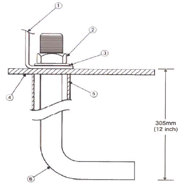
Use 16mm or anchored mounting bolts to secure the generator.
The 38mm x 152mm pipe inserted over the mounting bolts to align them to the holes in the bedframe. (see fig. below)
Vibration Isolator Installation
Place the vibration isolator (FSR Mounting – Free Standing Bolted) under the support point of the equipment, ensure that the load is uniformly distributed over the top plate of the vibration isolator as shown in Figure A and B below:
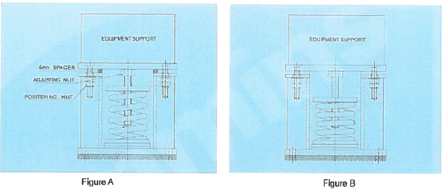
Adjust the FSR mounting: With the 6 mm spacer in position as shown, tighten the positioning nut.
Turn, adjusting bolt of the spring counter-clockwise to load the spring.
Load all the FSR at the same time to ensure that the total load is uniformly spread onto all the FSR mounts.
Continue until the spring load equal to the load of the requirement.
When the equilibrium point is reached, the 6 mm spacer can be removed from the FSR mount (see fig B above).
Moving the Generator Set
Ensure that the crane operating area is able to support the mass of the crane and the generator set.
Attach the lifting device to the lifting points only, using suitable shackles, chains and spreader bars.
Slowly tighten the slings.
Inspect the lifting attachments before commencing a full lift to ensure they are attached correctly.
Hoist generator set slowly using the indicated lifting points only.
Guide the generator set with ropes at a safe distance, to prevent uncontrolled rotation when positioning the generator set.
Move the generator set on the desired location and place in position, bring the set down slowly.
Loosen the slings, unhook and remove the shackles.
Mechanical Connections to Diesel Generator DG Set
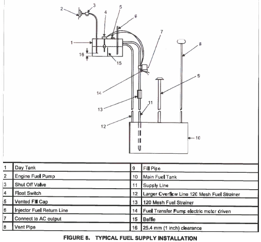
Fuel system: Cleanliness is of the utmost importance. Make every effort to prevent entrance of moisture, dirt or contaminants of any kind into the fuel system. Clean all fuel system components before installing
Fuel Return Restriction Limit: Fuel return drain restriction between the engine injector return line connection and the fuel tank must not exceed the limit stated in the model-specific generator set specification sheet.
Fuel Lines Routing: A flexible fuel hose or section of flexible fuel hose must be used between the engine’s fuel system and the fuel supply and return lines to protect the fuel system from damaged.
Engine Fuel Connection: Identification tags are attached to the fuel supply line connection. All generator set require a fuel return line from injector to the tank.
DC Control Wiring
TB1 Remote Monitor / Control Connection – Customer monitor/control connections are attached to terminal block TB1. Optional Equipment such as sensing devices used to monitor generator set operation, remote start/stop switches, etc. are also attached to TB1.
TB1 Wiring: Digital Connection. Connection points, other than relayed outputs and network are considered digital connection to terminal strip TB1. The type/gauge wire to be used for these connection are:
- Less then 305 meters, (1000 feet) use 20 gauge stranded copper wire
- 305 to 610 meters (1000 to 2000 feet), use 18 gauge stranded copper wire
Relay Due to wide variety of devices that can be attached to the relay outputs of TB1, installer must determine the gauge of the stranded copper wire that will be used at the site installation.
AC Electrical Connections
Before making any AC electrical connections, ensure that the generator set cannot be accidentally started.
Make sure the operator panel is in OFF mode.
Turn off or remove AC power from the battery charger and then remove the negative(-) battery cable from the set starting battery.
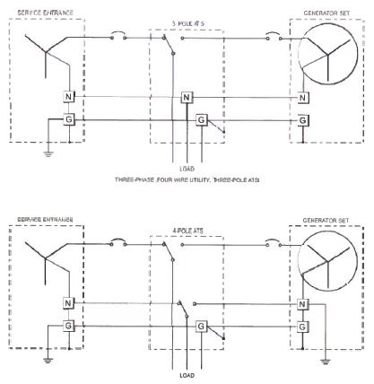
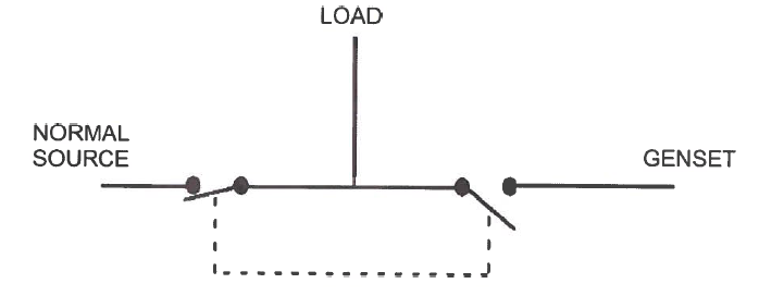
Transfer switch: Transfer switch must be used for switching the load from normal power source to the generator set (see figure below)
Load Connection
All loads are connected to the generator by bolting stranded load wire to the appropriate terminals on the generator re-connection terminal block or circuit breaker lugs.
The terminal are marked U, V, W and N to indicate the line and neutral connection (reference: U, V, W and N correspond with L1, L2 and L3; and N with LO respectively)
Grounding
The figure below shows the description of system and equipment grounding of permanently installed AC generators within facility wiring system.
It also illustrates typical system grounding for a 3 pole ATS, note that the generator neutral is connected to the ATS and it is not bonded to the ground at the generator.
In the 4 pole ATS system, grounding electrode conductor and bonding jumper are used to connect the generator neutral to ground.