
The speed of a dc shunt motor is directly proportional to the back emf and inversely proportional to the flux per pole. DC shunt motors are very useful and important part of any motor application. The motor speed control in dc shunt motor is very crucial because it impacts the use and design of the mechanical part of its application purpose.
We know the Back Emf,
Eb = PØNZ/60A
where, P = no. of poles,
Ø = flux/pole,
N = speed in rpm,
Z = no. of armature conductors,
A = parallel paths
Eb can also be given as,
Eb = V- IaRa
thus, from the above equations
N = Eb 60A/PØZ but, for a DC motor A, P and Z are constants
Therefore, N ∝ K Eb/Ø (where, K=constant)
Speed Control of DC Shunt Motor
There are three method which are famous for motor speed control i.e. flux control, armature control and voltage control.
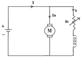
Flux Control Method: To control the flux, a rheostat is added in series with the field winding, as shown in the circuit diagram. Adding more resistance in series with the field winding will increase the speed as it decreases the flux.
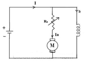
Armature Control Method: When the supply voltage V and the armature resistance Ra are kept constant, speed is directly proportional to the armature current Ia. Thus, if we add a resistance in series with the armature, Ia decreases and, hence, the speed also decreases.
Voltage Control Methods for DC Shunt Motor Speed Control
This method of speed control for dc motors involves further two principles as below:
a. Multiple voltage control
In this method of motor speed control, the shunt field is connected to a fixed exciting voltage and armature is supplied with different voltages. Voltage across armature is changed with the help of a suitable switchgear.
b. Ward-Leonard System
This system is useful where very sensitive speed control of motor is the requirement (e.g electric excavators, elevators etc.). The arrangement of components in this system is shown in the figure below:
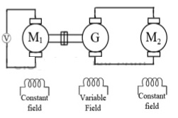
M2 is the motor whose speed control is required. M1 may be any AC motor or DC motor with constant speed. G is a generator directly coupled to M1.
Sharing is caring:

Discover more from Electrical Engineering 123
Subscribe to get the latest posts to your email.