
At the stage of receiving the cables at project site, inspect the protective covering on the cable for evidence of shipment damage. Leave the factory-applied protective cover in place until removal is absolutely necessary. Where possible, check the copper sheath for evidence of shipment damage.
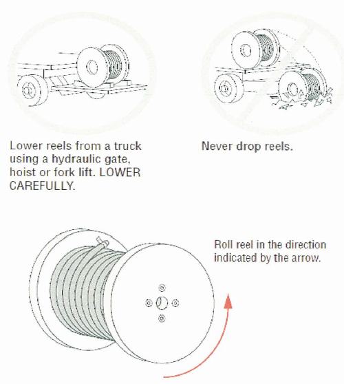
When cable drums are unloaded in designated area, provide wooden block below the cable drum to prevent it from rolling and before removing the hoist cable, check the direction of arrow on the drum. It must be the same direction as the pull.
Jack-up the cable drum by means of hydraulic jack enough to give clearance from the floor.
Remove the wooden cover of the cable drum. Select the required pulling grip, when selecting a pulling grip, it is extremely important to select a grip of the correct type, size and maximum rated capacity. Measure the circumference of the cable and find the correct size.
To protect cables from physical damage and the environmental effects, store indoors and protect from moisture, construction equipment, falling objects, chemical spills, moving vehicles, and other hazards.
Store cables indoors in a dry location. Do not stack reels. Ensure that both ends of the cable are securely fastened to the reel flange. Do not remove heat shrinkable end caps until ready to terminate the cable.
Plant / Equipment Requirements for cable installation work
- Electrician hand tools
- Steel pull spring
- Cable rollers
- Cable drums jack
- Handling equipment of drums
- Calibrated megger & millimeter
- Hydraulic cable cutter
- Winch motor where as required location
- Cable basket
- Cable pulling compound
- Screw driver
- Power Supply: Single-phase normal power where it is needed.
- Working platforms: scaffolding as required within the specific work area.
Care While Moving Coils and Reels
- Handle and install cables within suitable temperature limits
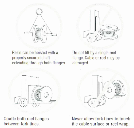
- Handle coils and reels utilizing equipment designed for that purpose.
- Do not drop coils or reels from any height, particularly from trucks or other transporting equipment.
- Lift or handle coils and cable reels in such a manner that the lifting / handling device does not make direct contact with the cable or its protective covering. Coils should be placed on a skid.
- Handle reels in a manner that prevents deterioration of and physical damage to the reel and to the cable.
- Take precautions to ensure that the flange of one reel does not impact the cable on another reel.
- If a coil or reel is dropped or the protective covering is damaged, examine the cable for damage. Damaged cables may need to be repaired or replaced.
The following lifting methods for reels are recommended:
Insert a suitable properly-secured shaft through the reel arbor hole and lift with slings using a crane or boom-type equipment. Use a spreader or other device to minimize sling pressure against the reel flange.
Move smaller, narrower reels using a forklift. Place fork tines so that lifting pressure is on both reel flanges, not on the cable.
Cable installations must be pre-planned to ensure a successful installation. It is important to ensure that personnel are properly trained and qualified for the specific task they are performing.
When installing cables, all appropriate precautions should be followed, including HSE and other applicable local safety regulations.
Therefore, in addition to observing standard safety practices, observe the following:
- Take reasonable precautions to prevent damage to the cable from severe blows with sharp instruments and pulling over sharp objects.
- Do not pull cables around corners that have sharp edges, or other obstructions.
- Pull all cable diameters, one at a time, by hand.
- Hand feed cables around corners using large sweeping bends.
- When changing direction from horizontal to vertical, use properly-sized sheaves or pulleys.
- Protect exposed cables from any nearby or overhead work that could damage the cable.
- Do not pull cables around a radius smaller than the minimum pulling radius.
- Make sure all equipment used during cable installation is in good operating condition
Preparing for Cable Pulling
Remove all steel binding straps, retaining battens and timbers.
Any exposed projecting nails must be removed. Ensure that cable containment is cleared from any sharp edge to eliminate damage or scratches on the insulation cables.
Install the cable roller on the cable tray on the entire cable laying area. Provide cable roller interval at 3 meters for straight run and corner cable roller on every change in direction.
Connect the pulling rope to the cable grip using shackle and provide signal on other end of the rope for cable pulling.
Installation Procedure of Cables & Wires in Conduit & Trunking
All electrical wiring will be in accordance with the specifications requirements and approved load schedules.
Cables will be approved and material inspection will be completed in advance of installation.
If winch motor to be used in cable pulling use a cable basket for gripping the cable.
Cable installation will be carried out by skilled and suitably experienced electricians under the supervision of highly competent site supervisors and engineers to ensure the correctness and quality of installation.
Prior to commencement of cable installation work, conduits shall be inspected to make sure that they have not been damaged or blocked. Trunking will be raised for inspection and approvals as well to ensure correctness.
No wires will be drawn through unless conduit and trunking installations have been completed and inspected and cleaned.
Wiring will only be carried out after the conduit installations and plaster work is completed.
Where single core PVC insulated wires are enclosed within the conduit and trunking, care will be taken that no damage will occur to the wires during the installation.
All wiring contained in conduit and trunking will be manually pulled by means of approved pulling material such as nylon cord and pull spring so that cable will not be damaged.
Conductors will be identified by means of color coding in accordance with the local regulation.
Proper color coding will be maintained throughout the installation. Color coding will be observed as follows:
Red Phase 1
Yellow Phase 2
Blue Phase 3
Black Neutral
Green/Yellow Earth
Measure the conduit and trunking length and check the correct size of the cable (as per approved drawings or load schedules) before cutting the wires.
Only consultant approved lubricants made for the purpose of pulling wires will be used to assist the drawing of wires.
Tie the cut wire to the rope and pull it until it reaches the end points. No more than one circuit will run in one conduit unless otherwise specifically permitted. Wires will be pulled simultaneously to conduit or trunking.
While preparing cable ends, ensure that conductor strands are not damaged and the strands are twisted together with pliers to ensure neat and firm connection.
Provide a name tag sticker in easy visible location on the trunking, tray etc. for identification reference prior to the ceiling final closure and inspection.
While removing the conductor insulation, ensure that no excess exposed conductor left.
Wires would be in drums and to be fixed in cable stands holders and site engineer to check wire length and wire splicing will not be allowed throughout the installation.
Once the circuits are pulled in the trunking, pull box and panels, side will be grouped by using the appropriate cable ties.
All cables will be clearly marked on both ends with the suitable cable markers or masking tape indicating the source and destination.
Once cable pulling is completed, trunking cover and end cap will be provided as well as cable tray end cap.
All unused holes in the trunking, if not required to be covered and grommeted.
After the completion of installation, inspection request will be raised to the consultant to ensure accuracy and quality of work.
Cable testing will be carried out afterward in accordance to approved test plan.
Installation Procedures for Power Cables
In cables of different voltages, if the insulation is lower than the voltage run of the adjacent cable they would be installed in a separate raceway or containment.
Heat resistant cables will be used for wiring from lighting fixtures to lighting points and from all spur outlets to equipment’s served like FCU’s and kitchen equipment’s.
Fire resistant cables will be used for power supply cable feeding power to electrical and mechanical equipment’s such as emergency lights, elevators, smoked fans, pressurization fans among others. Fire resistant cables will be installed in all fire safety corridors.
Instrumentation, automation and control cables will be installed in compliance to BS 5308 or equivalent.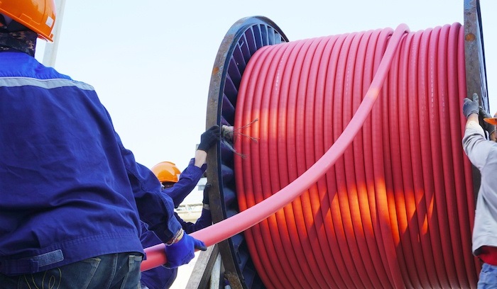
All horizontal and vertical installation of cables to cable trays and cable ladders will be supported using approved cable tie for LV and cable cleats for MV.
Care will be taken during installation so that cables are not subjected to tension and or mechanical stresses. Pulling lubricant to be used with UL listed category and consultant approved in pulling the cables in conduit.
If cables are cleated directly on the soffit, the cleating supports will be installed at regular intervals.
Cable drums will be positioned as close as possible to the installation area. Care will be taken care during transportation of cable drums. Where cable rollers to be used, it will be position at suitable intervals and secure them for installation on cable tray.
For long runs where recommended tension values may be exceeded, intermediate pulling will be implemented by arranging the cable in loop, tension indicator will be provided.
Where change of elevation or direction take place, cables will be supported and guided by corner type of rollers to prevent stress or damage during the pulling.
Cables will not be bended to a radius smaller than values recommended by the manufacturer. Also it will be ensured that no twisting of armored cable take place.
Care will be taken to ensure that external sheath is not damaged during cable pulling. Cable tags will be installed on both ends of the cable. All installed cables to be sealed at both ends by proper end caps shrouded to avoid dirt, debris and water accumulation.
Cable passing through fire rated walls will be sealed with fire barriers of approved type.
Segregation and correct distance between cabling run will be maintained according to the normal practice and standard.
If surface run for the cabling works, protective cover to be used to avoid direct sunlight exposure.
Ample length for the final cut allowance for the cable will be provided as required:
- 2.5mm2 to 6mm2 = 15cm
- 10mm2 to 16mm2 = 25cm
- Larger than 16mm2 = 45cm
Indoor trenches cabling will be segregated and run on trays or bracket secured to the trench wall. No cable will be allowed to be laid directly on the indoor trench.
20% of spare capacity will be provided to all containment for future use as per BS 7671 requirement in wiring regulation.
After the completion of installation, inspection request will be raised to the consultant to ensure accuracy and quality of work.
Cable testing will be carried out afterward in accordance to approved test plan.
Installation of Power Cables & Wires
Ensure during cable pulling that cables are properly aligned and no cable twisting will occurs. Use cable lubricant recommended by the manufacturer to help pulling tensions down.
After the cable has reached the other end, measure the required length for termination to the Equipment or Distribution board.
Provide adequate allowance for every termination point before cutting the cable at cable drum end.
Arrange the cable on the cable tray with approved cable spacing as per standards and specification. Layout of cables must follow as per design / installation drawings.
Where cable trays pass through floor or walls of a specific fire resistance, install the approved fire stopping materials as per manufacturer’s recommendation.
After obtaining the measurement, cut the cable from the drum and separate each phase of the cable in preparation for another insulation test.
After cutting the cable separate each stranded and performs for another initial insulation test. Record all the testing result. After testing seal both end of the cable with PVC insulation tape.
Provide proper cable identification and markings to prevent any obstruction and protection from any damage.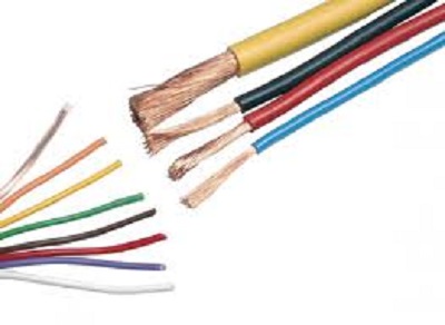
When work is completed, the work will be inspected and snagged by inspection team and any works found not compliant will be replaced or fixed before the final inspection is raised.
Ensure that all punch items have been cleared, all inspection records are signed and accepted by the client. Check that the signatures of the competent client inspector obtained where applicable and MEP Clearance can be given and the system is released for subsequent activities.
Cable Termination Method
Tools for the cutting and stripping of cable or wire includes wire stripper/cutter tools and retractable knives.
Use of the wire stripper/cutter tool is preferred to the retractable knife for the stripping and cutting of cable or wire for safety reasons.
Cutting of power cables
The wire stripper/cutter tool is used in the following manner for preparing cable or wire ends for termination:
- Determine the correct cable core or wire size prior to inserting the cable core or wire ends into the tool head for stripping.
- Squeeze the tool handles until the cable sheath or wire insulation is cut through to the metal.
- Stripping of cable core or wire ends is then carried out by removing the cut cable sheath or insulation.
- The cutting of the cable core or wire using the tool cutter is carried out by inserting the end into the tool head cutter blades and then squeezing the tool handles.
- Where it is not possible, because of cable size or availability, the use of retractable knife is acceptable for wire stripper/cutter tool.
- It is important that in using this tool, care is taken in order to avoid injury.
- Blade of knife should be retracted or covered with suitable protective cover when not in use, at all times.
