Cable tray / raceway is integral part of any cable management system. Selection of cable tray is very critical because if cable tray size is not sufficient the cables may become damaged due to improper handling and excessive heating etc. On the other hand cable tray supporting system can not be neglected as well since it ensures the integrity of whole cable management installations.
The the following sections of this page tables and formulas are provided to help determine how many cables can be safely carried by each size wire mesh / cable tray. This page also guides to determine the appropriate distance between supports for the load, based on number of cables, cable tray size, and bracket type.
Wire Mesh Cable Tray Fill Ratio = Cross section of cable / Cross section of tray
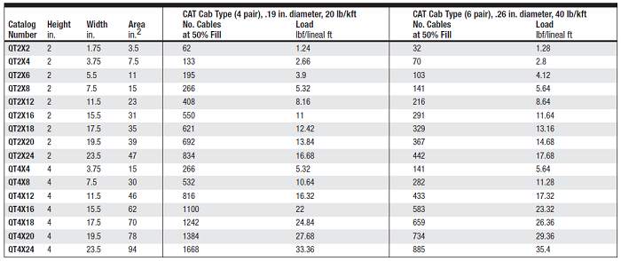
According to NEC 392.9 (B), when using ventilated tray with multi conductor control cable, the sum of the cross sectional areas shall not exceed 50 percent of the interior cross section of the cable raceway / tray. The Wire Mesh / Cable Tray Fill table in below section shows the number of cables and the load in lbf/lineal foot developed by typical 4 pair and 6 pair cable weighing 20 lb/kft and 40 lb/kft, respectively. While this table is a useful guide, actual loads must be calculated using the cable specified for any project.
Cable tray fill calculator
Use the following formula to calculate the number of cables that will result in a particular fill ratio, where:
A = Inside tray area, in in.2
D = Cable diameter, in inches
F = Fill ratio in %
N= Number of cables
The formula for number of cables is
N= ( F/100 ) * ( A ) /[(D/2)2 * Π]
EXAMPLE:
The installation will use CAT cable at .19 in. diameter, 20 lb per 1000 ft2. The desired fill ratio is 40%. The wire mesh
cable tray is 2 in. (51mm) high by 2 in. (51mm) wide.
A = 3.5 in.2
D = .19 in.
F = 40%
N = ( 40/100 ) * ( 3.5 / [(.19/2)2 * Π]) = 49 cables
Cable Load / foot = 49 cables * 20 lb/1000 ft. = 0.98 lb/ft
Below is the data for Quick Tray Wire Mesh Cable Tray Fill Table at 50% Fills. This table for cable tray sizes is provided by Hoffman Enclosures Inc. which is subject to change at any time.
Cable Raceway / Tray Support Calculations
Cable Tray is sized based on the number and type of cables required for the current and future need. A 50% fill ratio should equal the maximum number of cables pulled in a given cross section. Straight section supports installed at 5-foot (1.5m) centers are typical.
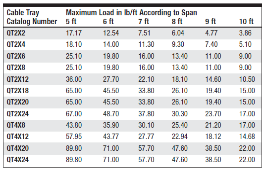
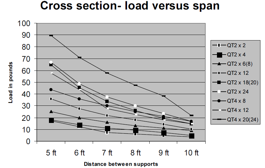
For support spans greater than 5 feet (1.5m), cable loads must be evaluated to ensure that the span between the supports is suitable for the load.
The support and anchor must be evaluated separately.
Supports should be placed within 24 in. (610mm) of a splice on straight sections, and the span between supports should not exceed the length of tray.
Additional supports will be required around bends and when the cable tray level changes.
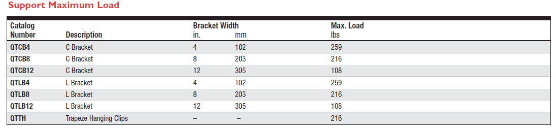
The load ratings of the hardware that supports the cable tray must also be considered.
Load ratings for some commonly used supports are shown in the tray support maximum load table in below section.
Once the load/foot has been determined, the weight on each cable tray support can be determined by multiplying the load/foot by the number of feet between supports.
Cable Tray Support Load Calculation Example
Weight of span = Load/foot * No. ft between supports
Load/foot figure from the 2 x 2 in. cable tray with 40% fill ratio example: 0.98 lb/ft
Weight of span = .98 * 5 = 4.9 lb
Weight on support = weight of span / 2