What Are Cable Trays?
An assembly of units/sections with associated fittings that form a rigid structural system to securely fasten or support cables.
Think of a roadway bridge that supports traffic.
Cable Tray Systems must provide protection to life & property against faults caused by electrical disturbances Lighting and failures which are part of the system Failure for equipment connected to the system to drain off excessive high voltages.
What is a Cable Tray System?
As per the National Electrical Code, a cable tray system is “a unit or assembly of units or sections and associated fittings forming a rigid structural system used to securely fasten or support cables and raceways.
” What does this mean?
Cable trays support cable the way that roadway bridges support traffic.
A bridge is a structure that provides safe passage for traffic across open spans.
Cable tray is the bridge that allows for safe transport of wires across open spans.
Standards / guidelines for cable tray systems
The National Electrical Code publishes the standards for all types of electrical applications.
Articles 318, 250, and 800 cover various aspects of cable tray systems.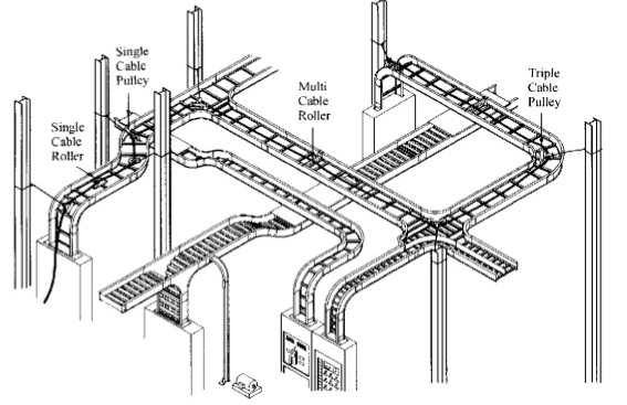
NEMA, (National Electrical Manufacturers Association), is an association comprised of the major cable tray manufacturers in the industry.
This committee has published three documents to date: NEMA VE1, FG1 and VE2.
NEMA VE1 Covers general cable tray definitions, manufacturing standards, performance standards, test standards, and application information.
NEMA FG1 Addresses the standards for fiberglass cable tray systems.
NEMA VE2 Covers cable tray installation guideline which covers receiving unloading and storage of materials.
Types of Cable Trays
- Ladder Tray
- Solid Bottom Cable Tray
- Trough ( ventilated ) Cable Tray
- Channel ( perforated )Cable Tray
- Wire Mesh Cable Tray
- Single Rail Cable Tray
Ladder Cable Trays
Solid side rail protection and system strength with smooth radius fittings and a wide selection of materials and finishes.
Maximum strength for long span applications standard widths of 150, 300, 450, 600, 750, and 900 millimeters
Standard depths of 50, 75, 100, 125 and 150 millimeters
Standard lengths of 3 to 6 meters
Rung spacing of 150, 225, 300, and 450 millimeters
Ladder cable tray is generally used in applications with intermediate to long support spans, 3meters to 6 meters.
Solid Bottom Cable Trays
Non ventilated continuous support for delicate cables with added cable protection available in metallic and fiberglass.
Solid bottom metallic with solid metal covers for non plenum rated cable in environmental air areas.
Standard widths of 150, 300, 450, 600, 750, and 900 millimeters.
Standard depths of 75, 100, 125, and 150 inches
Standard lengths of 3, 6, meters
Solid Bottom cable tray is generally used for minimal heat generating Electrical or telecommunication applications with short to intermediate
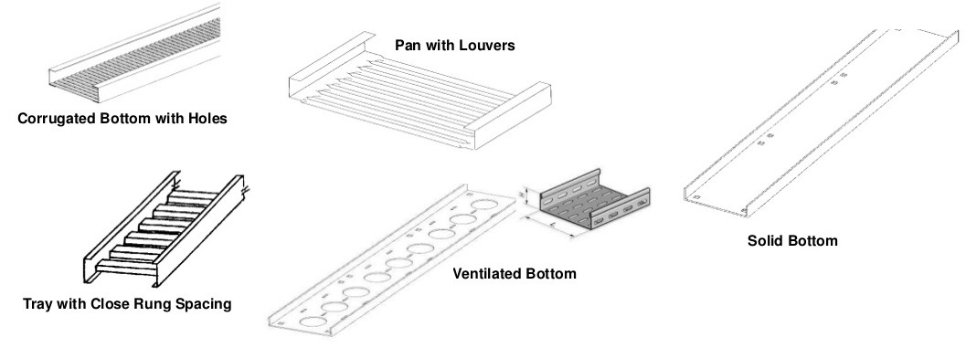
Trough Cable Trays
Moderate ventilation with added cable support frequency and with the bottom configuration providing cable support every 4 inches. Available in metal and nonmetallic materials.
Standard widths of 150, 300, 450, 600, 750, 900 millimeters
Standard depths of 75, 100, 125, and 150 millimeters
Standard lengths of , 3000, 6000 millimeters
Fixed rung spacing of 100 millimeters on center Trough cable tray is generally used for moderate heat generating applications with short to intermediate support spans of 0.6, 3, 6 meters.
Channel Cable Trays
Economical support for cable drops and branch cable runs from the backbone cable tray system.
Standard widths of 75, 100, and 150 millimeters in metal systems and up to 200 millimeters in nonmetallic systems.
Standard depths of 30 to 50 millimeters in metal systems and 25, 30, 40, and 50 millimeters in nonmetallic systems.
Standard length of 3, 4, and 6 meters Channel cable tray is used for installations with limited numbers of tray cable when conduit is undesirable.
Support frequency with short to medium support spans of 1.5 to 3 meters.
Wire Mesh Cable Trays
A job site, field adaptable support system primarily for low voltage, telecommunication and fiber optic cables.
These systems are typically steel wire mesh, zinc plated.
Available Standard widths of 25, 50, 150, 200, 300, 400, 450, 500, and 600 millimeters
Standard depths of 25, 50, and 100 millimeters
Available Standard length of about 3 meter Wire Mesh tray is generally used for telecommunication and fiber optic applications and are installed on short support spans, 1.2 to 2.4
Single Rail Cable Trays
These aluminum systems are the fastest systems to install and provide the maximum freedom fort cable to enter and exit the system.
These are single hung or wall mounted systems in single or multiple tiers.
Available standard widths are 6, 9, 12, 18, and 24 inches.
Standard depths are 3, 4, and 6 inches.
Common standard lengths are 10 and 12 feet. Single Rail Cable Tray is generally used for low voltage and power cables.
Common Materials of Cable Tray Systems
Steel (Min. Yield = 33KSI) (35 KSI for Stainless)
- Plain: hot rolled pickled and oiled steel.
- Pre-Galvanized: mill galvanized steel
- Hot Dip Galvanized After Fabrication
- Stainless Steel: type 304 or 316L fully annealed stainless steel
Aluminum (Min. Yield = 23 KSI): 6063-T6 or 5052-H32 alloy per ASTM B209
Fiber Reinforced Plastic (FRP)
- Polyester and Vinyl Ester resin systems available
- Meet ASTM E-84 smoke density rating; Polyester 680, Vinyl Ester1025
Cable trays are available in different configurations, straight sections are available to route cables in a horizontal or vertical plane.
Fittings are available to route cables in various directions in either the horizontal or vertical planes.
Typical examples of fittings include elbows, tees, crosses, and risers.
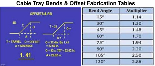
Each of these fittings are available in various radii and bend angles.
Covers are accessories and shouldn’t be in here unless splices etc. are included.
Cable Tray Installation Guidelines
The following tools are commonly used for installation of cable tray:
- Metal cutting saw
- Touch-up material
- Screwdriver
- Drill with bits
- File
- Open-end wrench
- Nylon cord or laser
- Sealant for cut edges(fiberglass)
- Cutting saw (for fiberglass), carbide- or diamond-tipped
- Leveling device
- Tape measure
- Square
- C clamp
- Torque wrench
- Ratchet wrench
- Offset bolt cutters (wire mesh)
- Dust mask (fiberglass)
- Appropriate safety equipment
Marking of Cable Tray using a square that reaches across the width of the cable tray, gauge off the edge of one side rail and mark both flanges.
Mark the web of the rail.
Marking can be done with a scribe, marking pen, or a pencil.
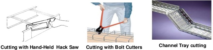
Cutting can be made using a hand-held hack saw, a circular saw with carbide-tip or diamond-dusted blade, a hand-held band saw, offset bolt cutters, or a high-speed grinder (for wire mesh only).
It is important to get a square cut to ensure a good splice connection.
Cable tray manufacturers offer jigs and other devices to aid in field cutting.
After cutting, smooth the cut edges to remove any burrs.
Fiberglass material should be cut with a circular saw with a carbide tip or a diamond dusted blade.
Drilling Holes for splice plates must be drilled in field-cut cable trays.
The most common method of locating the hole positions is to use a splice plate as a template.
Drill jigs are also available.
A short piece of side rail that is punched with the standard factory hole pattern can be bolted to the splice plate to serve as a stop that rests against the end of the field-cut side rail Clamp the splice plate to the rail, and drill through the splice plate holes and the side rail.
The correct drill size depends on the hardware supplied with the cable tray.
Match the holes that exist in the cable tray. After drilling, remove burrs.
Installation Steps of Cable Tray/Ladder/Trunking/Wire Basket
Mark the route of the tray.
Mark the position of the support system fixing points.
Drill the anchor fixing holes and insert the anchors.
Assemble and fit the support system as appropriate in accordance with the drawings i.e. Wall mounted, floor mounted or ceiling mounted, suspended from ceiling, single trays, Suspended from ceiling, multiple trays and/or bracket mounted.
Size bends to allow for the minimum permissible radius of the largest cable on the tray where cables shall retain their relative positions on bends and sweeps.
Where the support channels are cut or drilled protect the surfaces using Zinc enrich paint.
Fix the cable tray sections to the support system and joint the adjoining lengths in accordance with the drawing.
Fit correctly all earth continuity links.
Make expansion connections wherever cable tray and trunking are crossing building expansion joints.
Cable trays are to be made good at all joints or holes, first treat the surfaces with a suitable rust proofing agent.
Apply finishes comparable to the remainder of the surface.
Joints shall be positioned as close to the support as practical, and fixing of supports shall utilize “Rawl bolts” or equal.
Adjust the support system/tray fixings to the correct location and alignment.
Tighten all fixings and fastenings.
Carry out in-house inspection to ensure that the installation is satisfactory.
Mark the section/sections of cable tray flange to be removed.
Clamp the tray in a vise and cut the flange using a hack saw or jig saw.
Cable trays shall be cut along a line of plain metal and not through perforations.
Burrs or sharp edges shall be removed prior to the installation of tray sections or accessories.
Paint cut edges using the zinc enrich paint.
Assemble the sections in situ to form the bend or tee and bolt together in accordance with the drawing.
Where cables enter and leave cable trays be sure that no sharp edges exist and trays will carry the weight of the cables.
Check that no cables are subjected to any vibration or are in a position where they could be affected by sharp edges.
Provide Bushing through all holes cut in the body of the tray.
Where cable trays pass through walls of a specific fire resistance, install the approved fire stop materials.
Be sure that under no circumstances shall any copper sheathed cable or fitting be in direct contact with the galvanizing (in order to avoid any electrolytic action between dissimilar metals.)
Allow minimum space of 75 mm between trays and structures to provide for securing cable and for general maintenance.
Cable tray shall be fixed to the structure at not more than 3 meter intervals, depending on cable tray thickness.
Cutting of Stainless Steel Wire Mesh Cable Tray:
Field-fabricate changes in direction & elevation by cutting & bending cable tray.
Cut cable tray wires in accordance with manufacturer’s instructions.
Cut cable tray wires with side-action bolt cutters with offset head to ensure integrity of protective galvanic layer.
Remove burrs and sharp edges from cable trays.
Sizing of cable trays / ladders shall allow 40% spare capacity for future cables.
Where cables in tray pass through a floor or fire barrier, all openings will be sealed with approved fire stopping material.
Floor and Roof Installations
Cable tray should not be laid directly on the floor or roof.
It should be mounted far enough off the floor or roof to allow the cables to exit through the bottom of the cable tray.
If a strut is used for this purpose, mount the strut directly to the floor or roof and attach the cable tray to the strut using hold-down clamps and/or guide clamps.
Sharing is caring:

Discover more from Electrical Engineering 123
Subscribe to get the latest posts sent to your email.